
Bumper retainer

a technology of bumper retainer and retainer, which is applied in the direction of bumpers, vehicle components, vehicular safety arrangments, etc., can solve the problems of poor fastening strength, and inability to fasten a bumper retainer to a vehicle body. , to achieve the effect of improving the operation of mounting operation of the bumper cover, preventing the insertion of pins in the retainer unit, and convenient mounting

Active Publication Date: 2012-11-22
NEWFREY
View PDF4 Cites 6 Cited by
  • Summary
  • Abstract
  • Description
  • Claims
  • Application Information

AI Technical Summary

Benefits of technology

[0005]In the prior art technology, as mentioned in Patent Document 1, in order to mount a bumper cover on a body, a retainer has to be mounted on the body, and the bumper cover mounted on the retainer. In this way, the bumper cover is positioned and the body covered. (In other words, the bumper cover is accurately positioned and the external appearance of the body improved.) However, especially in the case of the rear bumper, holes are formed in the body and the bumper is mounted directly. As a result, sealing (waterproofing) is required. Usually, as mentioned in Patent Document 1, fasteners (screws) are fastened using a screwdriver. However, the bumper can also be fastened with tapping screws using an impact wrench. This generates axial force. Packing is set on the contact surface of the body to ensure a seal. Because a tool is required to mount the bumper on the retainer in Patent Document 1, the operational efficiency is lower.

Problems solved by technology

However, especially in the case of the rear bumper, holes are formed in the body and the bumper is mounted directly.
However, it does not fasten a bumper retainer to a vehicle body.
Because the fastening structure relies on a fastening clip structure in which an expandable cylindrical portion is expanded from the inside by a rotatable operating piece, the fastening strength is poor and waterproof performance is non-existent.

Method used


Image

  • Bumper retainer
  • Bumper retainer
  • Bumper retainer

Examples


Embodiment Construction

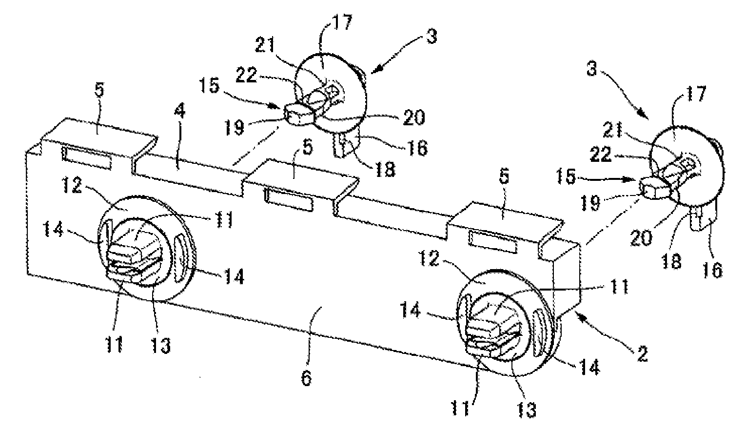
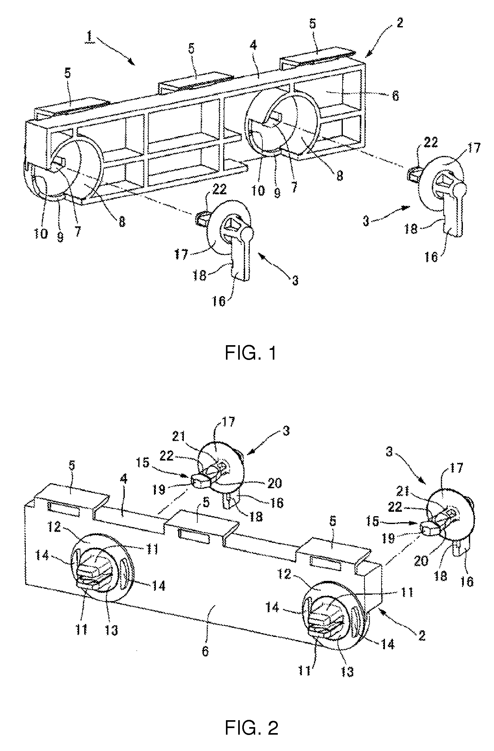
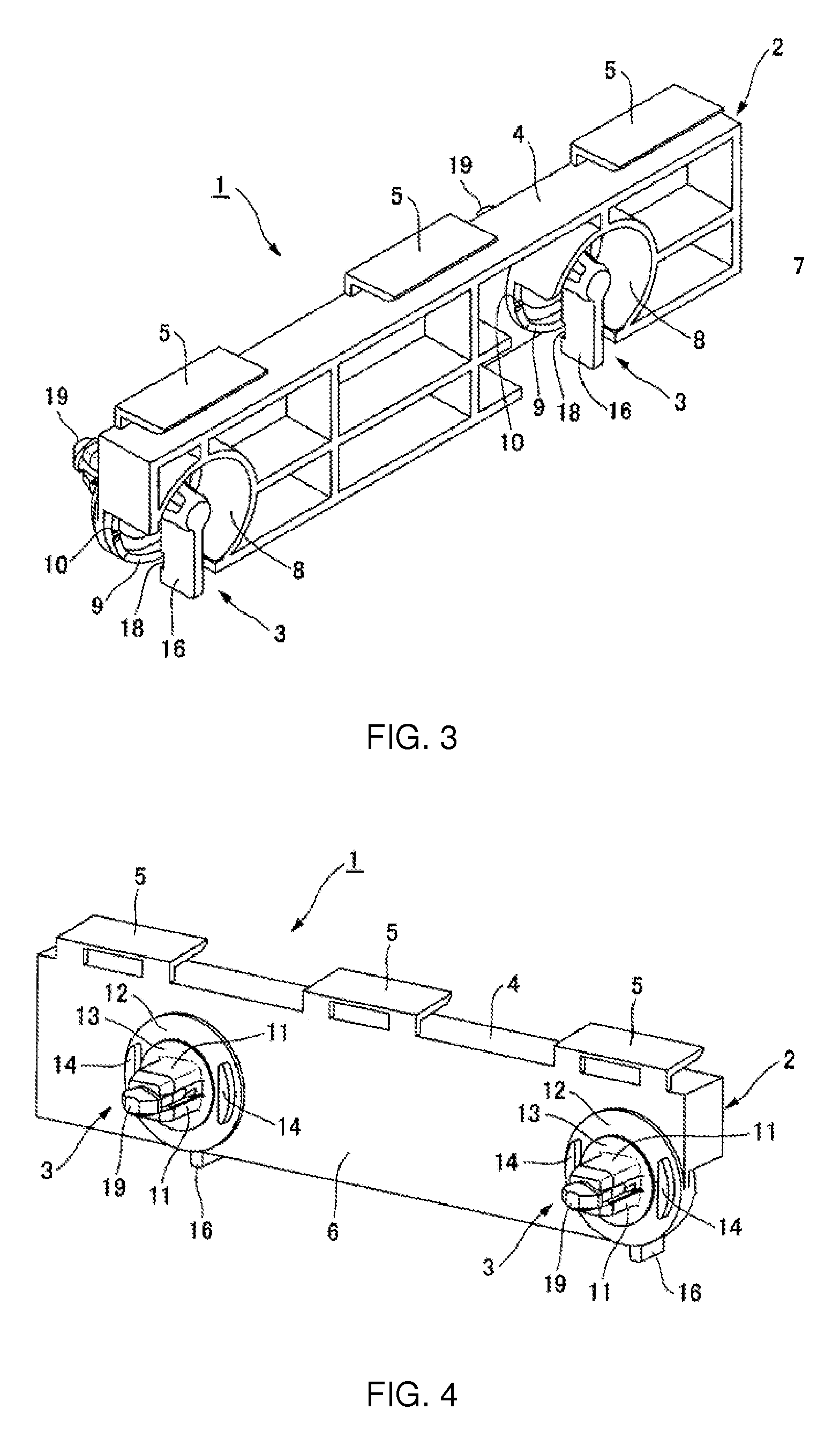
[0029]The following is an explanation of the bumper retainer in an embodiment of the present invention with reference to the drawings. First, the structure of the bumper retainer 1 will be explained with reference to FIG. 1 through FIG. 4.

[0030]As shown in FIG. 1 through FIG. 4, the bumper retainer 1 includes a retainer unit 2 and a pin member 3. In a typical bumper retainer 1, the pin member 3 is inserted into the retainer unit 2 (see FIG. 3 and FIG. 4). In the embodiment shown in the drawings, two pin members 3 are inserted into the retainer unit 2. However, the number of pin members 3 changes depending on the number of fastening locations in the body 30 for the bumper retainer 1 (see FIG. 5 through FIG. 8), that is, the number of mounting holes in the body 30.

[0031]As shown in FIG. 1, the retainer unit 2 has a C-shaped cross-sectional structure in which a recess is formed at the back on the body side facing outward from the vehicle. Securing hooks 5 are provided in the upper wall...


PUM


Abstract

When a retainer unit is fastened to a body, the rotation of a pin member around its longitudinal axis pushes out and widens the body mounting leg portion of the retainer unit, and the retainer unit is drawn into the body. As a result, the elastic flange of the leg is bent, the insertion hole in the body is sealed by the elastic flange of the leg, and infiltration of water from the outside is prevented. By drawing the retainer unit into the body, the pin member is also drawn into the body a slight distance (dimension α). As a result, the elastic flange of the pin member is bent, the pin insertion hole is sealed by the elastic flange of the pin member, and infiltration of water from the outside is prevented.

Description

CROSS-REFERENCE TO RELATED APPLICATIONS[0001]This application claims priority from Japanese Patent Application No. 2011-111526 filed on May 18, 2011, the disclosure of which is incorporated herein by reference.BACKGROUND OF THE INVENTION[0002]The present invention relates to a bumper retainer for mounting a bumper cover on a vehicle body and, more specifically, to a bumper cover mounted so as to be properly accommodated at a predetermined position on the body.[0003]In a bumper cover support structure for a vehicle in the prior art, the bumper cover is mounted on the body via a bumper cover support bracket or a bumper retainer. In a bumper cover support bracket, mounting holes are provided at a predetermined interval, and a grommet is integrally formed in each of these mounting holes. Mounting holes are provided at a predetermined interval in the bumper cover mounting portion of a body panel, the grommets formed in the bumper cover support bracket are inserted into these mounting hol...

Claims


Application Information

Patent Timeline
Patent Type & Authority Applications(United States)
IPC IPC(8): B60R19/36
CPCB60R2019/1886B60R19/24
Inventor SANO, TAKAHIRO
Owner NEWFREY
Learn More