
Printer and print-condition setting method for the same

a printing machine and printing technology, applied in the direction of digital output to print units, instruments, television systems, etc., can solve the problems of difficult to provide highly functional control panels, not user-friendly, and low production cos

Inactive Publication Date: 2005-09-27
138 EAST LCD ADVANCEMENTS LTD
View PDF4 Cites 41 Cited by
  • Summary
  • Abstract
  • Description
  • Claims
  • Application Information

AI Technical Summary

Benefits of technology

[0010]It is therefore an object of the invention to provide a method of readily selecting a desired print-condition file from a memory card with a plurality of print-condition files stored therein and a printer having a user interface arrangement for effecting the method.
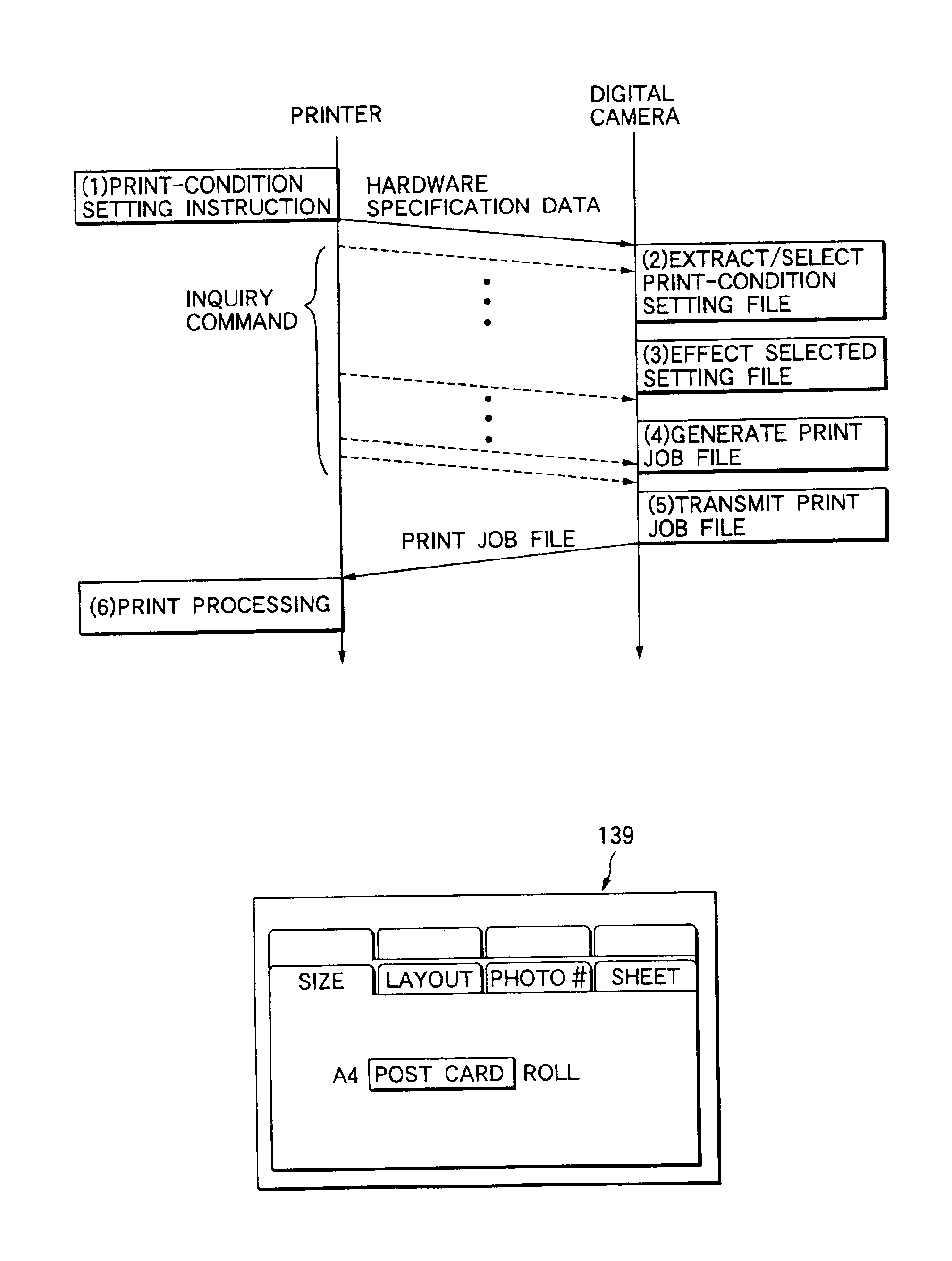
[0011]It is also an object of the invention to propose a method of readily selecting a desired print-condition file by using peripheral equipment connected via a communication interface and a printer for effecting the method.
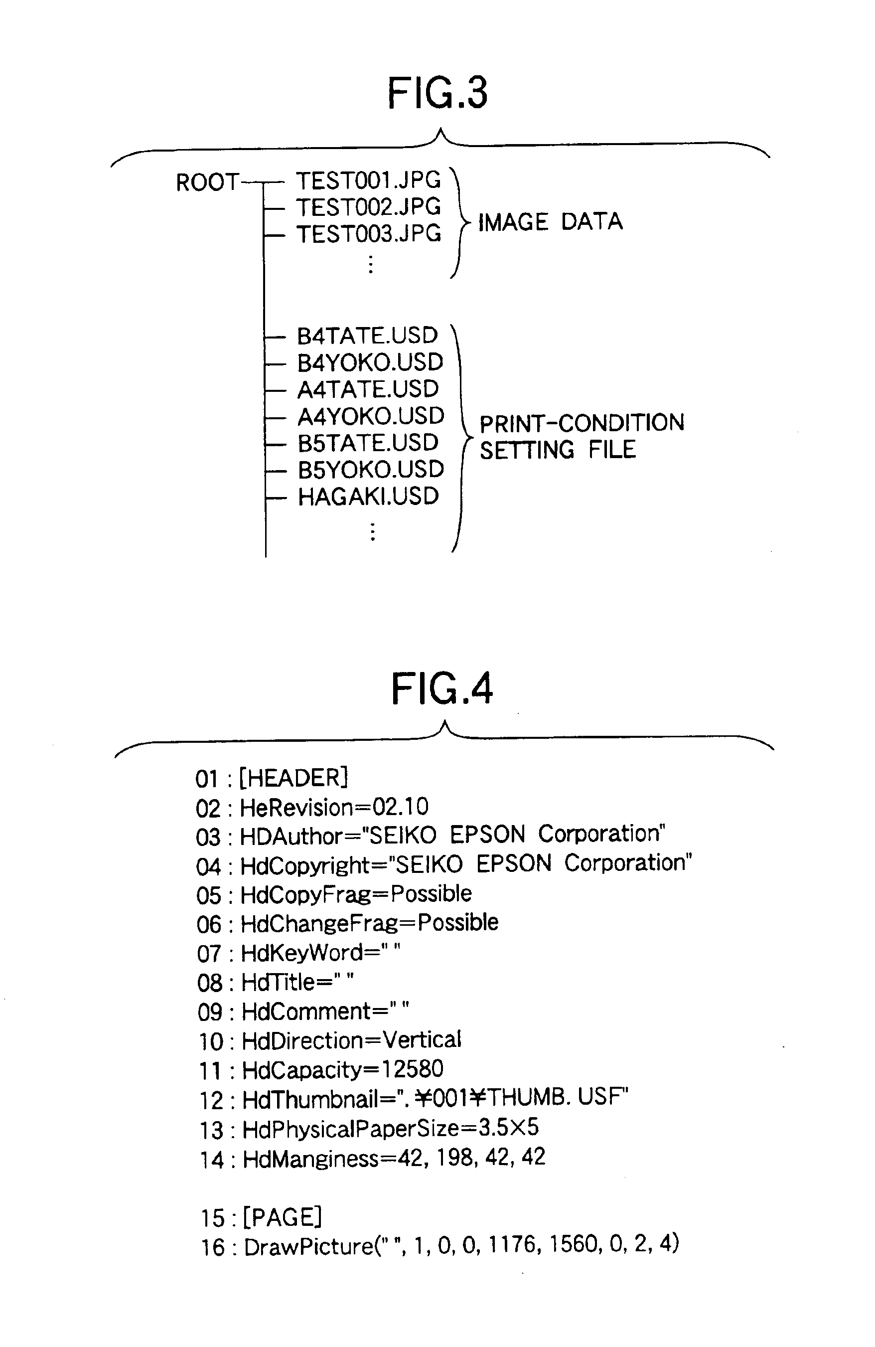
[0019]Accordingly, a desired print-condition script can readily be selected from the memory card stored with a plurality of print-condition scripts in the user interface of the printer.
[0059]In this configuration, since only the print-condition setting information is indicated, a desired print-condition file can readily be selected from the memory card stored with a plurality of print-condition files, in the interface of the peripheral device such as a digital camera connected to the printer.

Problems solved by technology

Although the stand-alone printer above is designed so that various print conditions can be set by a user through the control panel, it has been only possible to set the print conditions within a range of contents that have been incorporated into a control device in the printer body.
However, the control panel of the stand-alone printer is provided with only necessary and sufficient functions to achieve the original display / selection objective of setting various print conditions but still has a problem in that it is not user-friendly when a desired print-condition file is selected from the memory card with a plurality of print-condition files stored therein so as to set the desired print conditions.
Moreover, a highly functional control panel is difficult to provide in view of keeping the production cost lower.

Method used


Image

  • Printer and print-condition setting method for the same
  • Printer and print-condition setting method for the same
  • Printer and print-condition setting method for the same

Examples


Embodiment Construction

[0076]Preferred embodiments of the invention will now be described by reference to the accompanying drawings. However, the invention is not limited to these embodiments but intended to describe the invention by way of example. Moreover, the invention can be implemented in various modes without departing from the substance thereof.

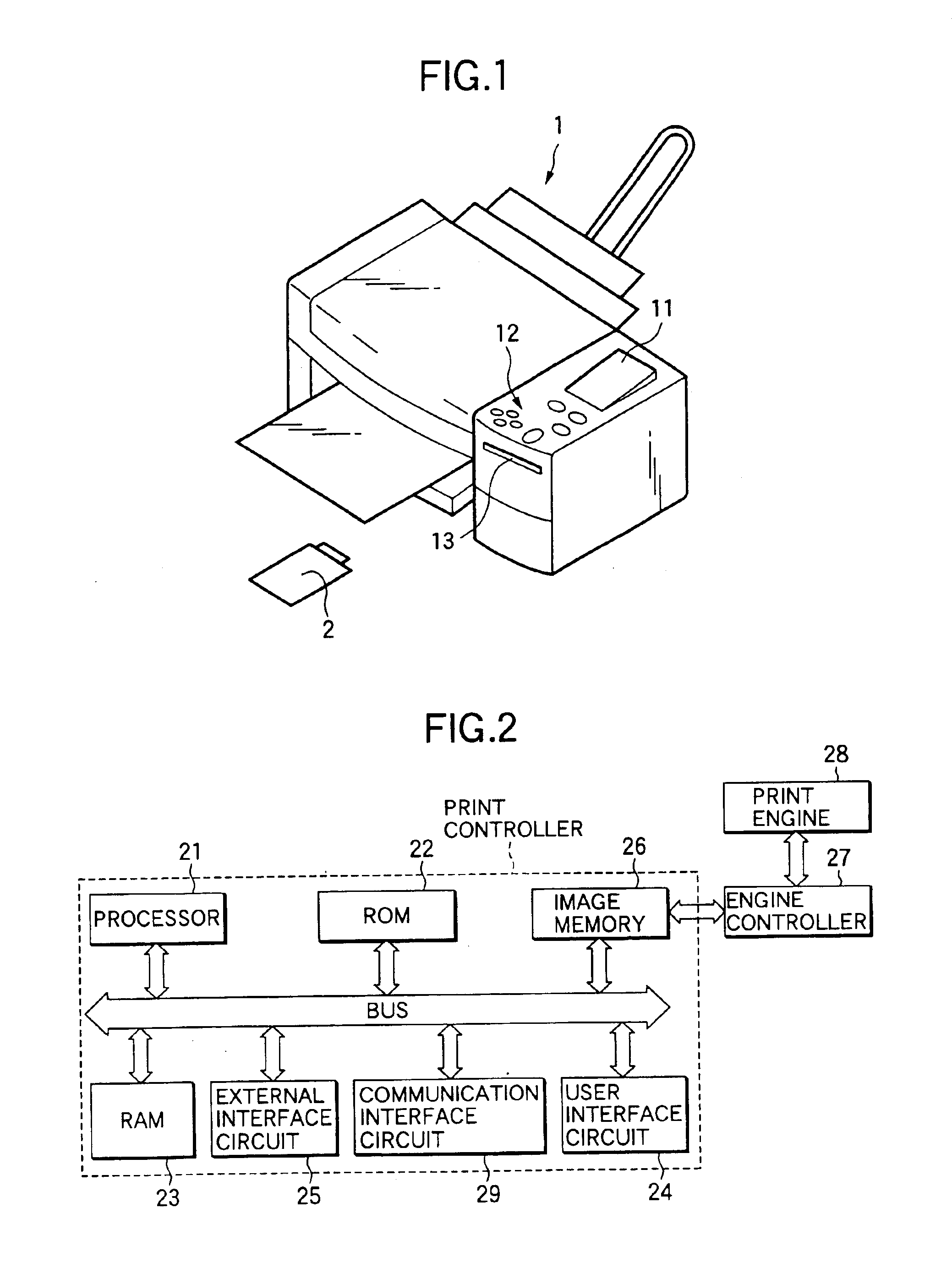
[0077]As shown in FIG. 1, a liquid crystal panel 11 and a plurality of buttons 12 are provided on the top face of a body of a printer 1 to form a user interface. In other words, a predetermined guidance message and so forth are displayed on the liquid crystal panel 11, so that a user is allowed to supply to the printer 1 print conditions and print instructions to be set interactively by pushing the buttons 12 in a manner corresponding to the contents displayed. Further a card slot 13 as an external interface is provided in the front body of the printer 1. The card slot 13 is in conformity with the PCMCIA standard and so arranged as to make replaceable a mem...


PUM


Abstract

An interface, to which a recording medium storing at least one first setting information item is removably attached to a printer. A storage stores hardware specification data. A reader reads out the at least one first setting information item from the recording medium attached to the interface. A register judges whether the at least one read out first setting information item matches with the hardware specification data, and registers the first setting information item which matches with the hardware specification data as at least one second setting information item. A selector selects one of the at least one second setting information item as a print condition.

Description

BACKGROUND OF THE INVENTION[0001]The present invention relates to a printer and a print-condition setting method for the printer, and more particularly to a printer capable of performing printing with an external memory medium such as a memory card attached to the printer according to print-condition setting information read from the external memory medium, and to a print-condition setting method for the printer.[0002]Further, the present invention relates to a printer capable of performing printing according to print-condition setting information set by peripheral equipment such as a digital still camera (hereinafter called the “digital camera”) to be connected via a communication interface and to a print-condition setting method for the printer.[0003]Stand-alone printers (sometimes called direct printers) capable of printing data on printing paper independently have come into wide used recently without the necessity of their being connected to host computers represented by persona...

Claims


Application Information

Patent Timeline
IPC IPC(8): G06K15/00B41J21/00G06F3/12B41J29/38G06K15/02H04N5/76
CPCG06K15/00G06K15/005G06K15/1806
Inventor NARUSAWA, HIDEYUKITANAKA, YOICHINISHIZAWA, HIDETAKEKOMAGAMINE, KATSUMI
Owner 138 EAST LCD ADVANCEMENTS LTD
Learn More