

Exercise methods and apparatus
a technology applied in the field of exercise methods and equipment, can solve problems such as the contrary of fixed aspect ratios to real life activities
- Summary
- Abstract
- Description
- Claims
- Application Information
AI Technical Summary
Benefits of technology
Problems solved by technology
Method used
Image

Examples
embodiment 300
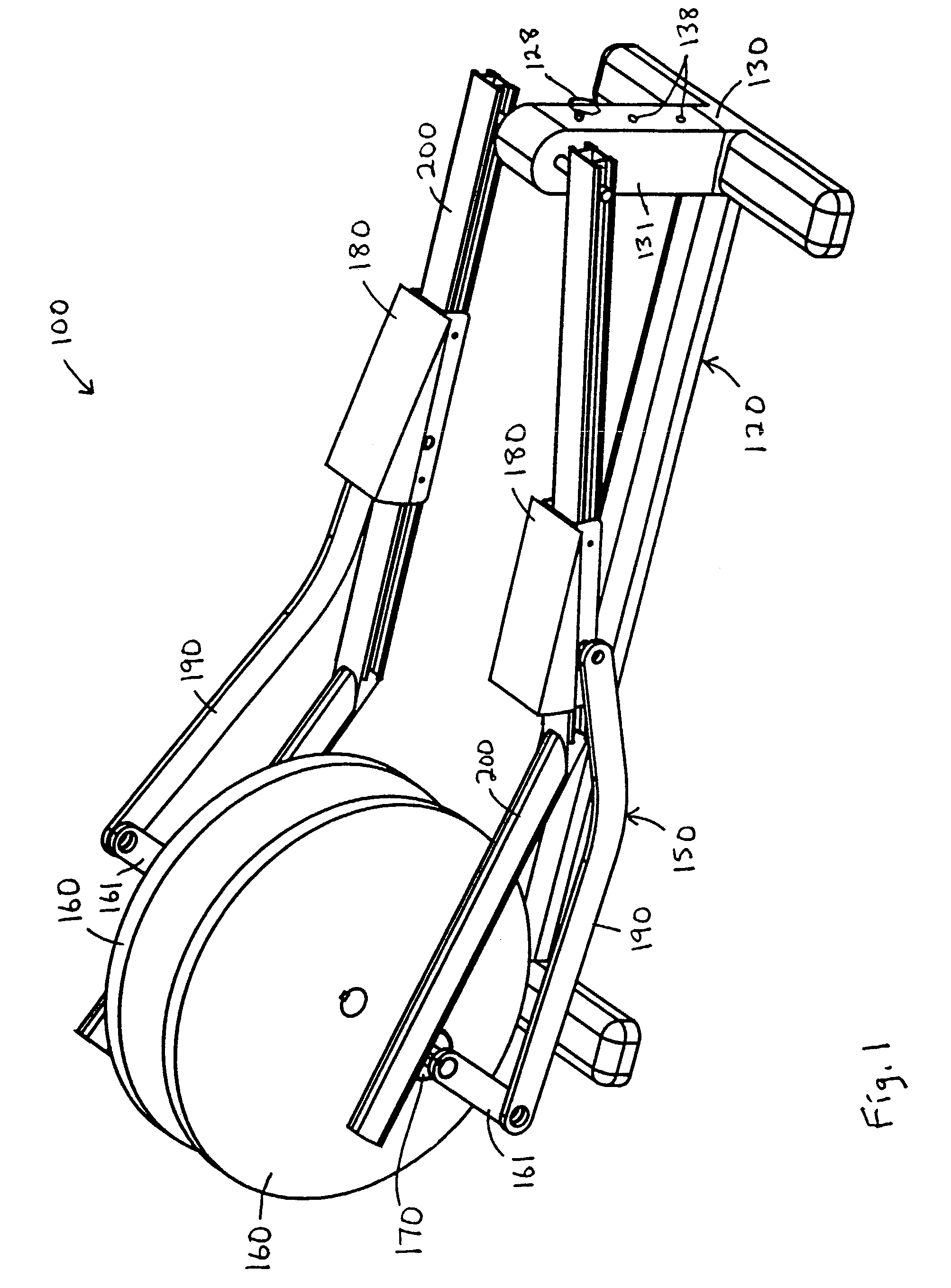
[0095]An opposite, forward end of the link 390 is rotatably connected to a force receiving member 380 that rolls along an intermediate portion 408 of a rail 400. A rearward end 406 of the rail 400 is supported on the roller 370. On this embodiment 300, a discrete segment 407 separates or offsets the rearward end 406 and the intermediate portion 408.
[0096]A forward end of the rail 400 is pivotally connected to a forward stanchion 330 on the frame 320 by means of a shaft 333. The handle member 430 is also pivotally connected to the forward stanchion 330 by means of the same shaft 333. As a result, the handle member 430 and the rail 400 independently pivot about a common pivot axis. The handle member 430 includes an upper, distal portion 434 which is sized and configured for grasping by a person standing on the force receiving member 380. In operation, the alternative embodiment 300 allows a person to selectively perform arm exercise (by pivoting the handle 430 back and forth), while a...
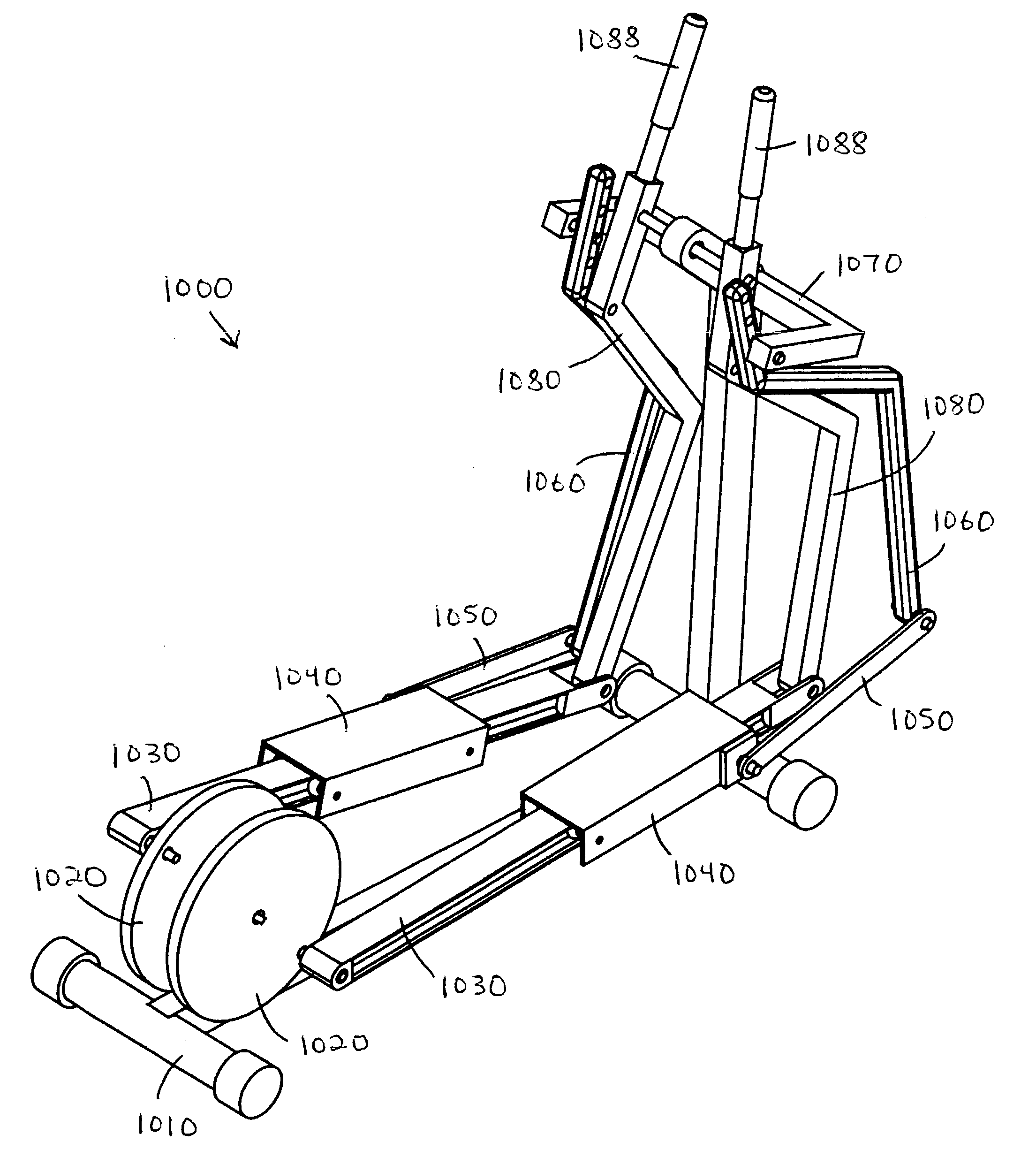
embodiment 1000
[0105]Left and right rails or links 1030 have rearward ends which are rotatably connected to radially displaced portions of respective cranks 1020. The resulting axes of rotation are disposed at a crank radius from the crank axis. Forward ends of the rails 1030 are constrained to move in reciprocal fashion relative to the frame 1010. Left and right foot supports or skates 1040 are movably mounted on intermediate portions of respective rails 1030. Each skate 1040 is sized and configured to support one foot of a standing person. On the embodiment 1000, opposing pairs of rollers are rotatably mounted on the skates 1040 and rollable along outwardly opening channels on the rails 1030.
[0106]Left and right drawbars or links 1050 have rearward ends rotatably connected to respective skates 1040; and forward ends rotatably connected to lower ends of respective rocker links 1060. Opposite, upper ends of the rocker links 1060 are rotatably connected to respective rocker links 1070 at pin joints...
embodiment 1200
[0116]Left and right rails or links 1230 have rearward ends which are rotatably connected to radially displaced portions of respective cranks 1220. The resulting axes of rotation are disposed at a crank radius from the crank axis. Forward ends of the rails 1230 are constrained to move in reciprocal fashion relative to the frame 1210. Left and right foot supports or skates 1240 are movably mounted on intermediate portions of respective rails 1230. Each skate 1240 is sized and configured to support one foot of a standing person. On the embodiment 1200, opposing pairs of rollers are rotatably mounted on the skates 1240 and rollable along channels on the rails 1230.
[0117]Left and right drawbars or links 1250 have rearward ends rotatably connected to respective skates 1240. Forward ends of the drawbars 1250 are rotatably connected to lower ends of respective support members 1270 and thereby define pivot axes P1. Opposite, upper ends of the support members 1270 are rigidly secured to resp...
PUM
 Abstract
Description
Claims
Application Information