Battery charge indicating circuit

a battery pack and charge indicator technology, applied in the field of electrochemicals, can solve the problems of operators being unsure of when battery packs need to be recharged, determining and unsure of the charge state of battery packs

Inactive Publication Date: 2005-09-27
CREDO TECH CORP
View PDF29 Cites 66 Cited by
  • Summary
  • Abstract
  • Description
  • Claims
  • Application Information

AI Technical Summary

Problems solved by technology

A common problem for users of such kits, however, is determining the charge states of the battery packs.
In some instances, operators may have not used the kits in some time, and thus are unsure of the charge state of the battery packs and may charge filly charged battery packs.
At other times, unless the battery packs are discharged resulting in the device being inoperable, operators may be unsure of when battery packs need to be recharged.
This can result in the battery packs being charged unnecessarily.

Method used


Image

  • Battery charge indicating circuit
  • Battery charge indicating circuit
  • Battery charge indicating circuit

Examples


Embodiment Construction

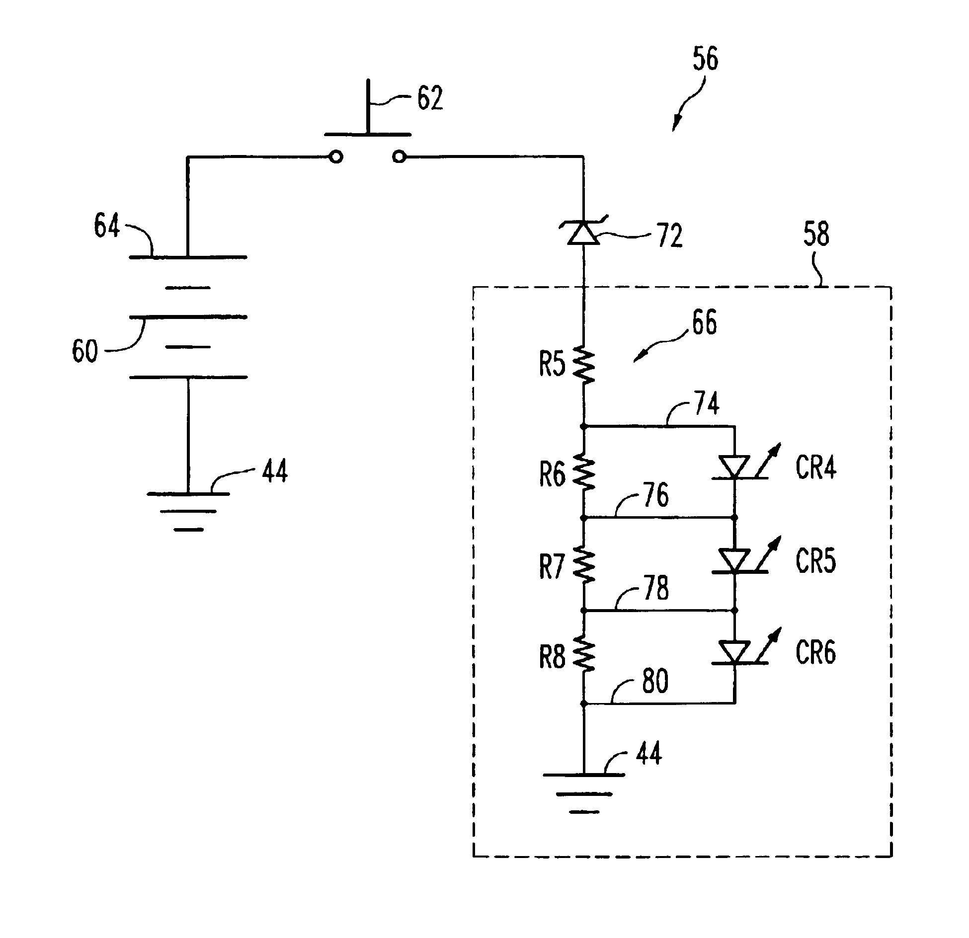
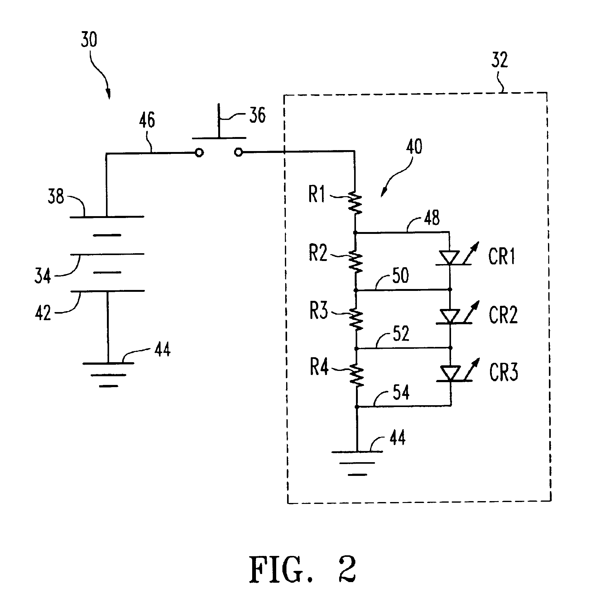
[0009]The present invention is directed to a voltage indicating circuit for use with a power source, such as a battery pack. Generally, many portable devices are powered by rechargeable battery packs that require intermittent charging throughout the lifetime of the battery packs. In order to provide optimal charging to these battery packs, different embodiments of voltage indicating circuits are disclosed herein which provide a visual display indicating a relative voltage level of a battery pack upon user activation of a switch. Preferably, the visual display is provided by light emitting diodes (LED's) that emit light in different combinations according to the relative voltage level of the battery pack.

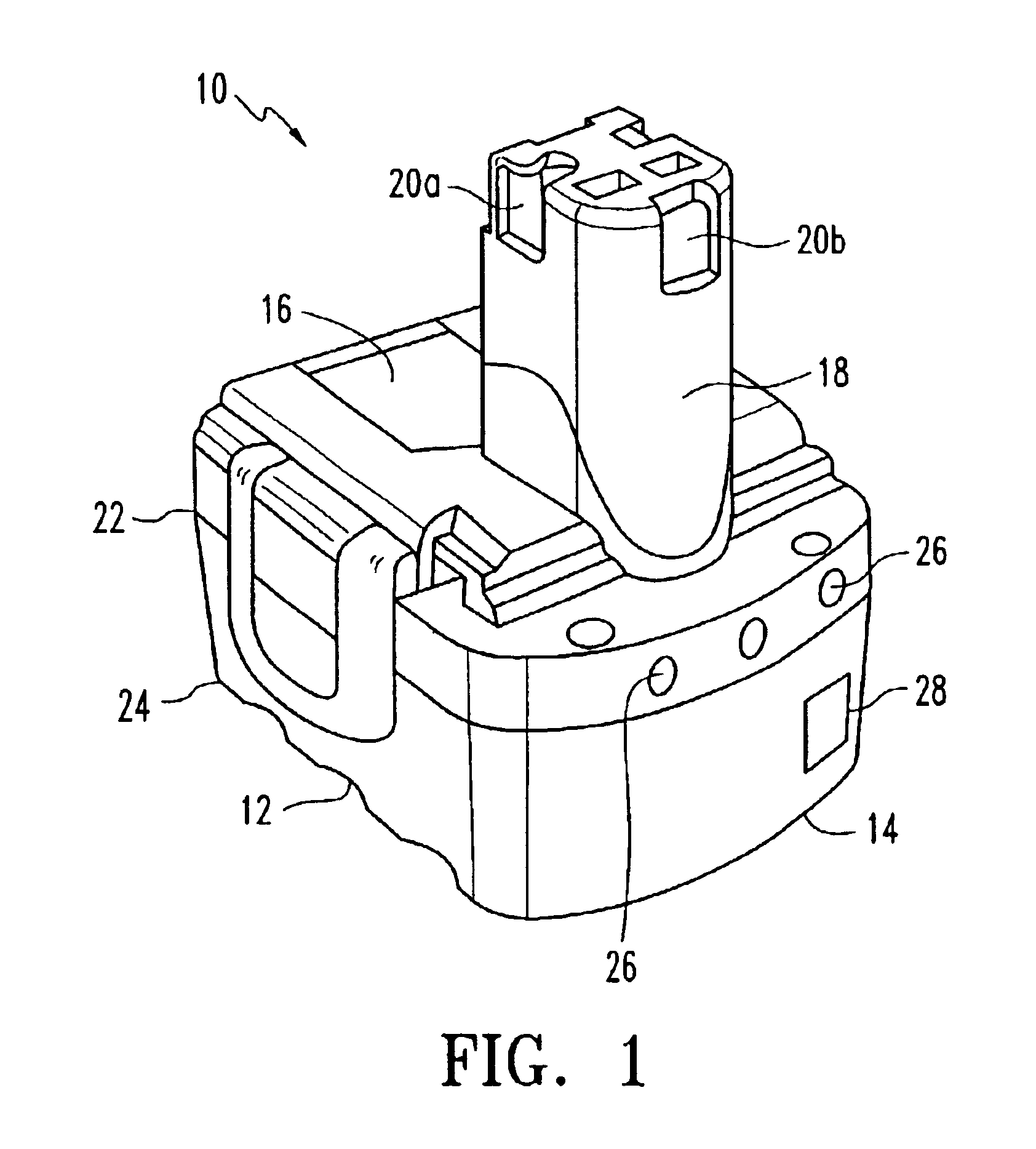
[0010]Turning now to FIG. 1, one embodiment of a battery having a charge indicating circuit, formed as a battery pack, is indicated generally at 10. The battery pack 10 includes a generally rectangular housing 12 having a bottom surface portion 14 and a top surface portion 16. Dispos...


PUM


Abstract

A voltage indicator circuit for indicating a charge state of a power supply, such as a battery pack, is disclosed. The voltage indicator circuit includes a voltage divider circuit that connects to a plurality of series connected light sources, such as light emitting diodes. Upon activation of the voltage divider circuit, one or more of the light sources may illuminate to provide a visual indication of the current charge state of the power supply. More particularly, the number of light sources illuminated varies according to the charge state of the battery pack.

Description

BACKGROUND OF THE INVENTION[0001]The present invention relates generally to electronics, and more specifically relates to a circuit for indicating a charge state of a battery pack used with battery power driven devices.[0002]There has been continued innovation in the field of battery packs, and especially rechargeable battery packs that are used with portable devices, such as cordless power tools. Examples of such rechargeable battery packs are those produced under the SKIL and BOSCH brands by the S-B Power Tool Corporation of Chicago, Ill., which are used with various cordless power tools also produced under the same brands. A typical rechargeable battery pack ordinarily has a generally rectangular housing and a male stem connector extending from a surface thereof. These battery packs commonly have an associated battery charger that is correspondingly sized and configured to contain a female slot for receiving the male stem connector of the battery pack. The battery packs are furth...

Claims


Application Information

Patent Timeline
Patent Type & Authority Patents(United States)
IPC IPC(8): G01R31/36
CPCG01R31/3637G01R31/3682G01R31/3646G01R31/388
Inventor KOVARIK, ILLYAGAWELL, GEORGE R.
Owner CREDO TECH CORP
Why Eureka
Try Eureka