
Method and apparatus for welding with battery power

a battery power and welding technology, applied in welding apparatus, arc welding apparatus, manufacturing tools, etc., can solve the problems of limited application of battery power welders, inability to provide a versatile, useful, welding source, and inability to provide auxiliary output for battery welders

Active Publication Date: 2007-08-09
ILLINOIS TOOL WORKS INC
View PDF27 Cites 184 Cited by
  • Summary
  • Abstract
  • Description
  • Claims
  • Application Information

AI Technical Summary

Benefits of technology

[0107] Numerous modifications may be made to the present invention which still fall within the intended scope hereof. Thus, it should be apparent that there has been provided in accordance with the present invention a method and apparatus for welding with a battery that fully satisfies the objectives and advantages set forth above. Although the invention has been described in conjunction with specific embodiments thereof, it is evident that many alternatives, modifications and variations will be apparent to those skilled in the art. Accordingly, it is intended to embrace all such alternatives, modifications and variations that fall within the spirit and broad scope of the appended claims.

Problems solved by technology

However, battery power welders have been of limited application because battery power does not lend itself to long term high power outputs such as welding, and the control of such systems has not been able to provide a versatile, useful, welding source.
Additionally, battery welders have not provided an AC auxiliary output (i.e., a 115 or 230 volt output that can be used as a substitute for utility power for tools, lights, etc.).
The engine driven welder / generator is often started and left running for the total duration of the welding task or other task requiring AC power, even though the demand for the welding power or AC power is of a limited sporadic nature.
This can lead to excess wear, fuel consumption, and noise.

Method used


Image

  • Method and apparatus for welding with battery power
  • Method and apparatus for welding with battery power
  • Method and apparatus for welding with battery power

Examples


Embodiment Construction

[0047] While the present invention will be illustrated with reference to particular components, topologies, controls, and applications, it should be understood at the outset that the invention may also be implemented with other components, topologies, controls and applications.

[0048] Generally, the invention relates to a welding power supply that includes a battery and / or an engine / generator and / or a vehicle for input power. Preferably, a battery charger is included (or provided by the user) to charge the battery. The source of power for the battery may also be used to supplement the battery power to provide welding power.

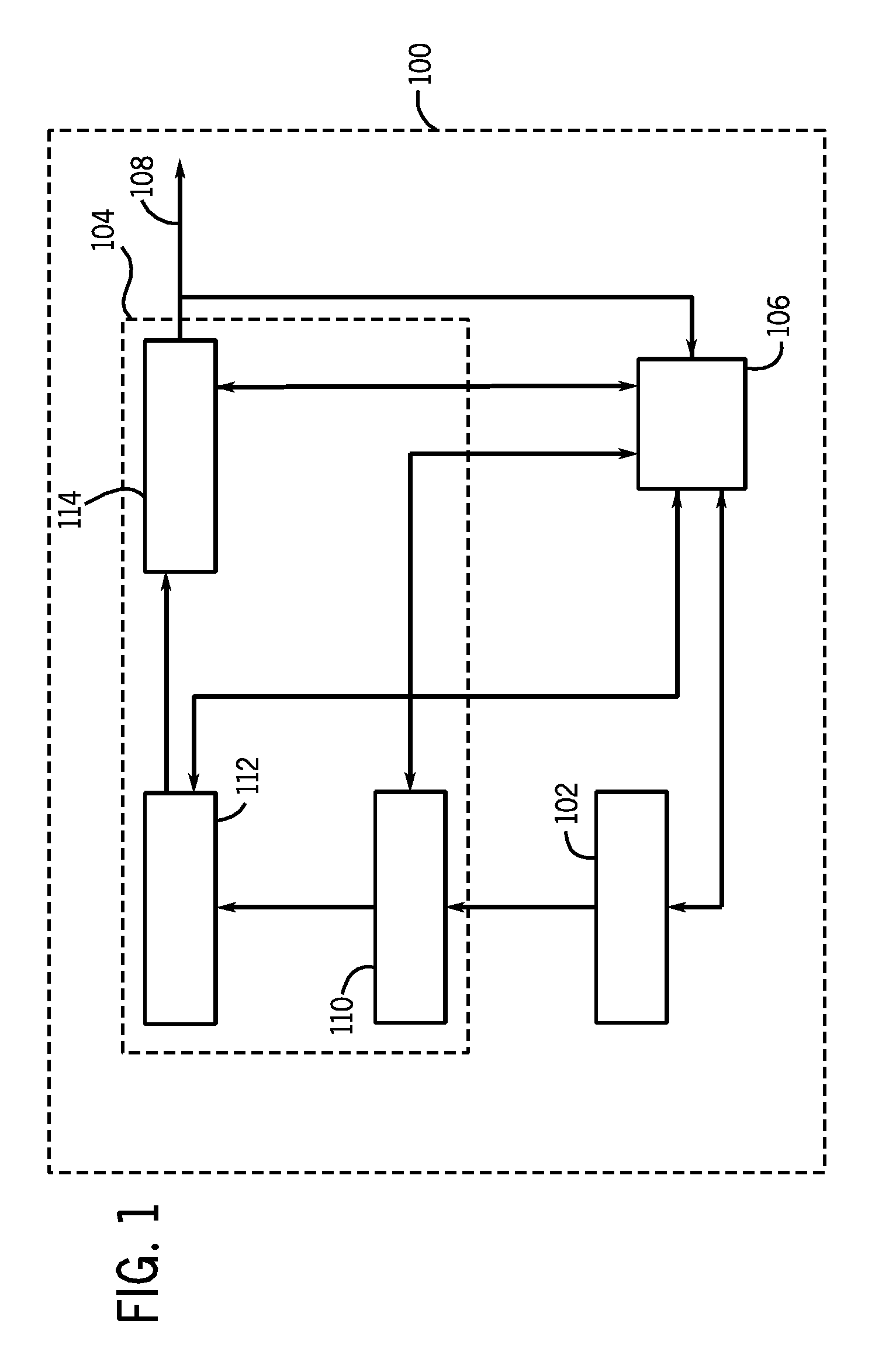
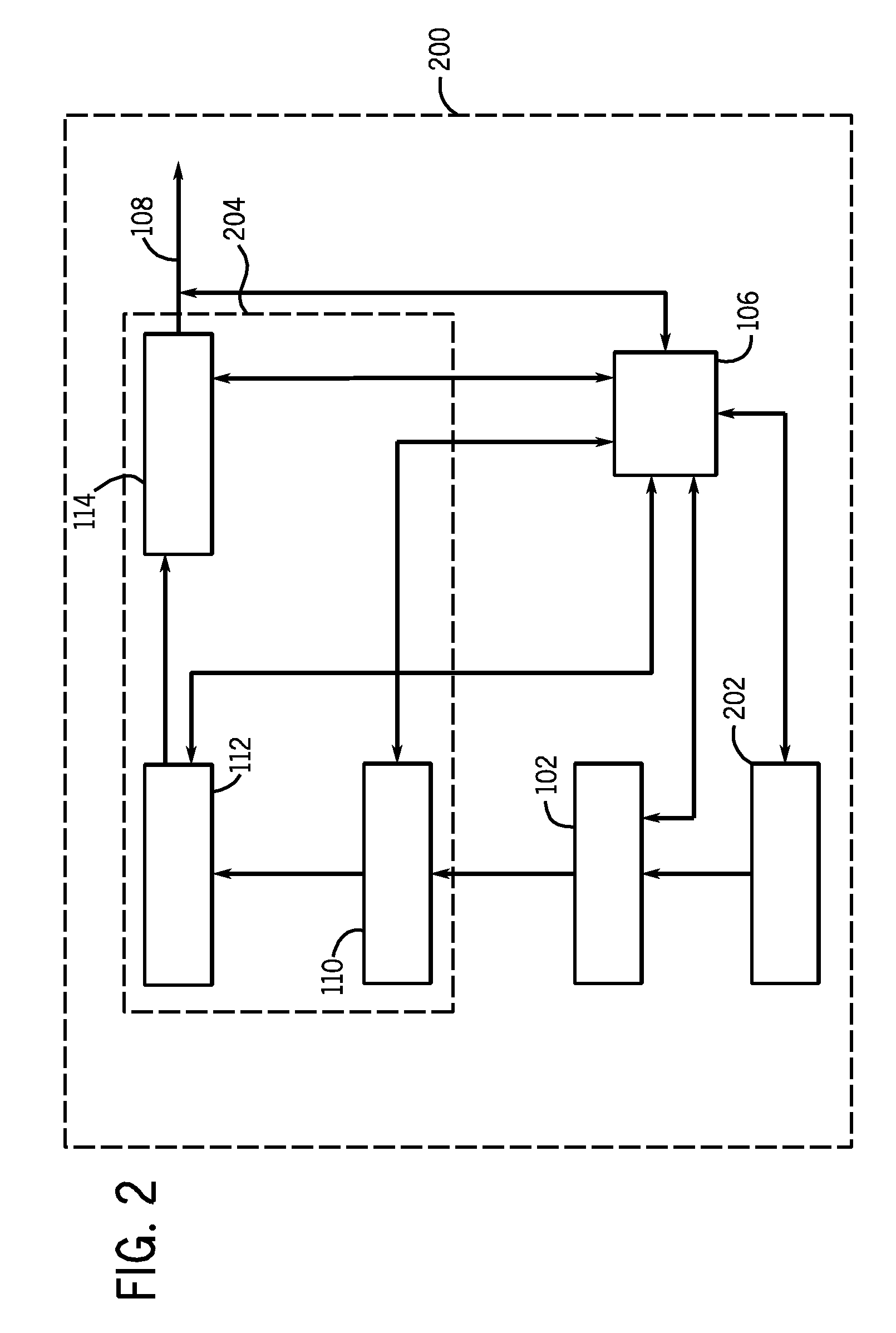
[0049] One embodiment provides for a welding-type power supply 100, shown in FIG. 1, that includes a battery (or other energy storage device) 102, a converter 104 and a controller 106, that cooperate to provide power to a welding-type output 108. Battery, as used herein, includes any type of battery. Energy storage device, as used herein, includes a device that s...


PUM

PropertyMeasurementUnit
Poweraaaaaaaaaa
Electric chargeaaaaaaaaaa
Electric potential / voltageaaaaaaaaaa

Abstract

A method and apparatus provides welding-type power and preferably includes a removable battery or other energy storage device, a converter connected to the battery, and a controller. The controller may have a CV and / or a CSC and / or an AC weld control module, and / or an ac auxiliary control module. The converter is a boost converter, a buck converter, a cuk converter, a forward converter, an inverter, a bridge converter, and / or a resonant converter. The controller may include a battery charging control module, and may have one or more charging schedules, and / or data for stored charge, thermal information, expected life of the battery, maximum amp-hour charge for the battery, maximum charging current and / or feedback. The battery charging schedules may include at least 3 phases, such as a phase of increasing voltage and a phase of decreasing current, a substantially constant power phase. The controller can wirelessly provide data to a display or pda. A generator may provide power to the battery, charger, and / or the weld. It can include a vehicle and use its dc power system.

Description

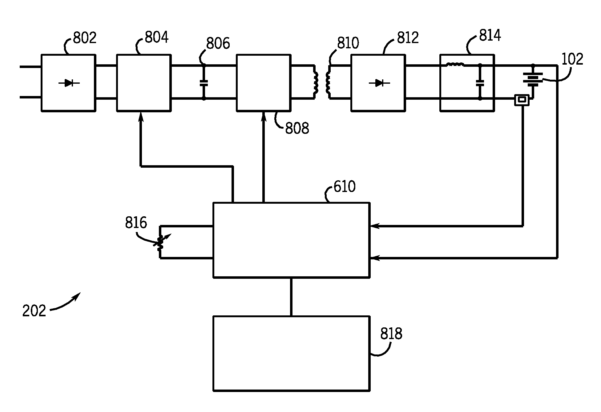
FIELD OF THE INVENTION [0001] The present invention relates generally to the art of welding-type power supplies. More specifically, it relates to welding-type power supplies that derive power from a battery or other energy storage device. BACKGROUND OF THE INVENTION [0002] There are many known welding-type power supplies used for many known applications. Often, a particular power supply will have a topology and a control scheme chosen or optimized for particular welding applications. For example, a welding power supply might be designed for CV welding, AC welding, CC welding, or controlled short circuit (CSC) welding. Welding-type power supply, as used herein, includes any device capable of supplying welding, plasma cutting, and / or induction heating power, as well as control circuitry and other ancillary circuitry associated therewith. [0003] Welding-type power supplies receive power and convert or transform that power into power suitable for welding. Known types of power supplies i...

Claims


Application Information

Patent Timeline
IPC IPC(8): B23K9/10
CPCB23K9/1081
Inventor VOGEL, BERNARD J.BEESON, RICHARD W.
Owner ILLINOIS TOOL WORKS INC
Learn More