[0017]Other systems and methods for providing constant power, improving efficiency, and overcoming the limitations of fixed displacement motors when operating over a wide
pressure range include using
active control with a VD hydraulic motor. For example, efficiency for an
electric motor-generator can vary substantially based on torque and RPM; when the hydraulic motor-pump in the staged hydraulic conversion system is attached to an
electric motor-generator, it would be advantageous to operate at a
narrow range or fixed value for RPM (e.g. 1800 RPM) and torque to operate at peak efficiency, increasing
electric motor, and thus system, efficiency. Likewise, operating at a fixed RPM and power (and thus
constant voltage, frequency, and current for an electric generator) during system
discharge would allow an electric generator to be synchronized with the grid and potentially eliminate additional power
conditioning equipment that would be required for a variable frequency, variable
voltage, and / or variable
power output. By using the VD hydraulic motor-pump in lieu of the FD hydraulic motor, the displacement per revolution can be controlled in such a way as to maintain a nearly
constant torque and proportionally increasing flow rate such that the RPM and
power output are kept nearly constant. For the novel
compressed air energy storage and
recovery system using staged hydraulic conversion described in the above-referenced applications, this constant RPM and power allows for a reduction in electric system costs by potentially eliminating power
conditioning equipment necessary for a variable frequency, voltage, or power output, while at the same time improving overall system efficiency by operating at the peak efficiency region of the electric generator; likewise, the increasing flow rate maintains a nearly constant power throughout a decreasing
pressure range, also adding value to the energy storage and recovery system.
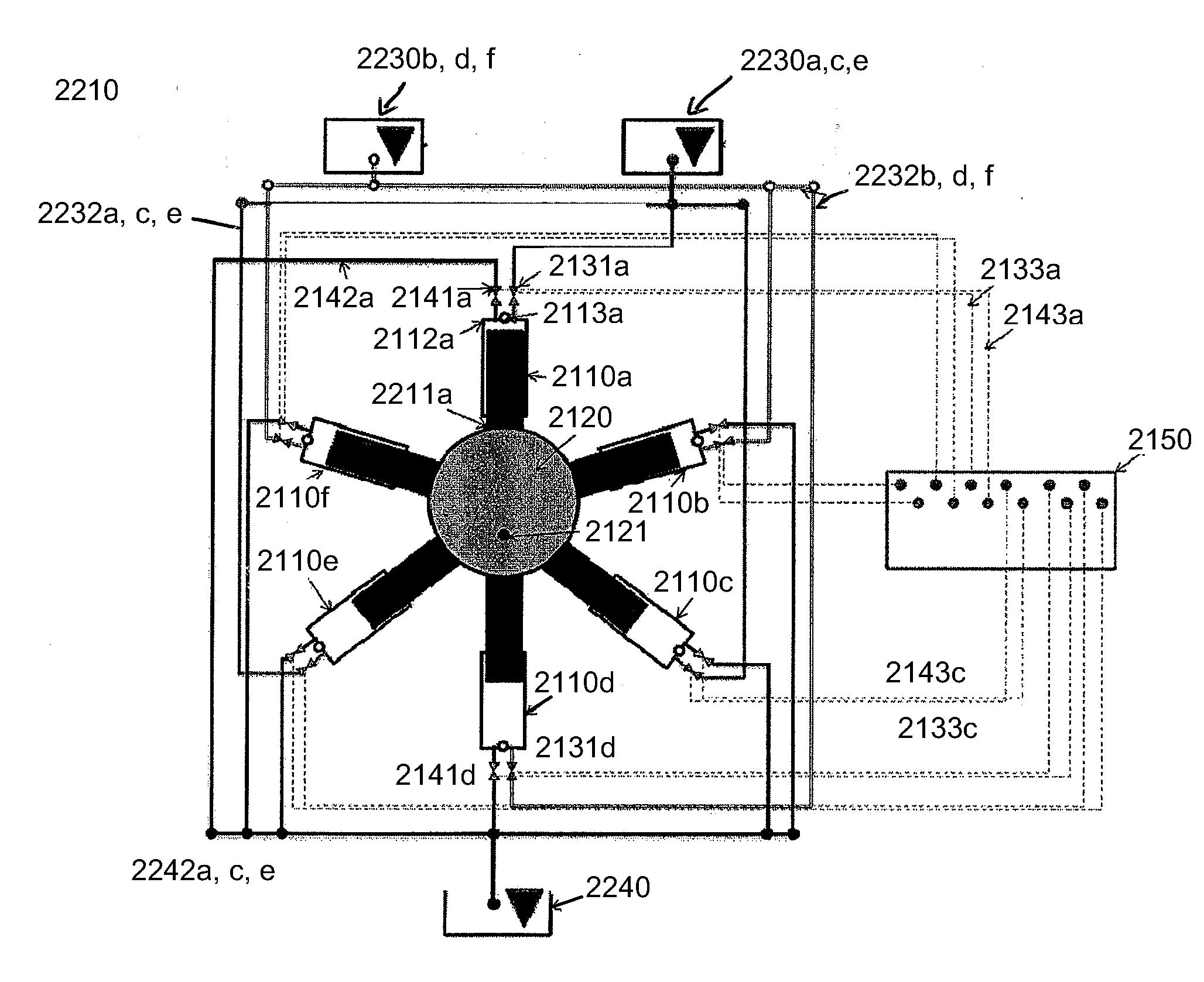
[0018]Furthermore, high efficiency standard commercial
variable displacement motor-pump designs include radial
piston style (external
cam), which are used primarily at low speeds, and axial
piston styles (
swash-plate, bent-axis). For axial
piston motors, the piston
assembly typically rotates in an
oil bath; for large displacement axial piston motors, viscous drag (which is proportional to speed squared) limits efficiency at high rotational speeds. Additionally, for the radial and axial piston styles displacement is reduced by reducing piston
stroke; as piston
stroke drops below half the total possible
stroke, efficiency typically drops substantially. As described herein, newly developed VD hydraulic motor-pumps which use
digital control to open and close valves to control displacement are able to achieve substantially higher efficiencies at large displacement sizes (no longer rotating the entire piston
assembly in an
oil bath) and maintain high efficiency at low relative displacements (by not changing piston stroke length). In these digitally controlled pumps / motors,
relative displacement is controlled by actively opening and closing valves to each piston, such that each piston may or may not be exposed to
high pressure each time the rotating
cam completes a revolution. Unlike the standard commercial VD motor-pumps, the piston always completes a full stroke, maintaining high motor-pump efficiency even at low relative displacements.
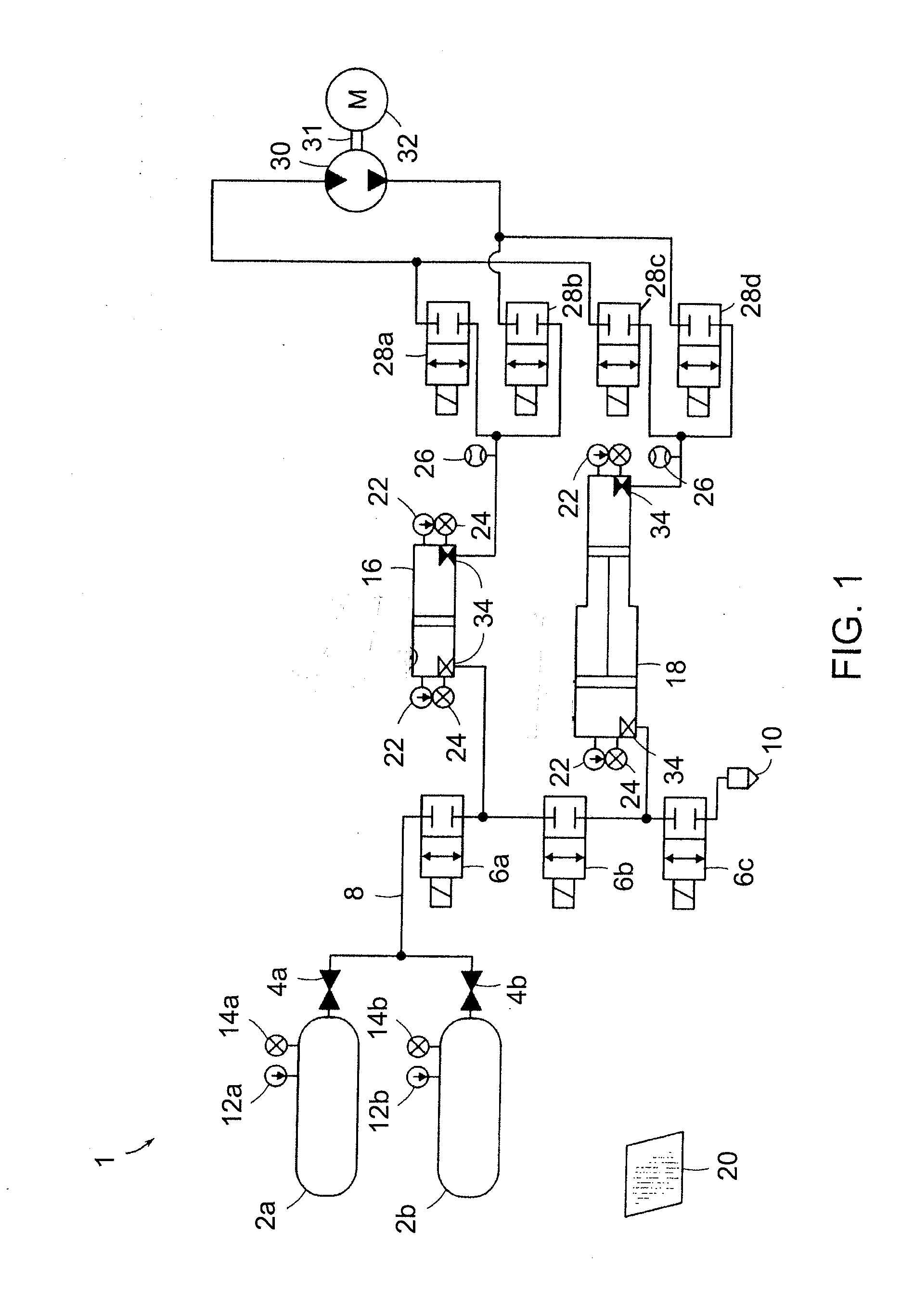
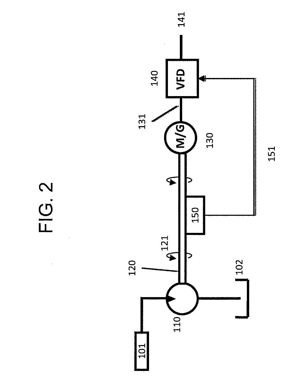
[0019]In one aspect, the invention relates to a system for providing a constant electrical output from a compressed gas energy storage and recovery system. The system includes a hydraulic-pneumatic energy storage and recovery system configured to provide a varying pressure profile at, at least one outlet, a variable displacement hydraulic motor-pump in fluid communication with the at least one outlet, and a control system in communication with the variable displacement hydraulic motor-pump. The control system controls at least one variable, such as pressure, piston position, power, flow rate, torque, RPM, current, voltage, frequency, and displacement per revolution. The use of the variable displacement hydraulic motor and associated control system allow a user to achieve near constant expansion and compression power in the hydraulic-pneumatic energy storage and recovery system, while maintaining near constant RPM or torque at the shaft of an electric motor-generator.


