Battery monitoring system with low power and end-of-life messaging and shutdown

a battery monitoring system and battery technology, applied in the direction of safety/protection circuits, instruments, transportation and packaging, etc., can solve the problems of battery's probable imminent failure, no messages are sent, and the battery's charge duration naturally decreases, so as to improve the ability to accurately monitor and manage battery use, the effect of ensuring the safety of the battery

Inactive Publication Date: 2006-04-04
OMNITRACS
View PDF10 Cites 191 Cited by
  • Summary
  • Abstract
  • Description
  • Claims
  • Application Information

AI Technical Summary

Benefits of technology

[0013]The invention affords its users with a number of distinct advantages. In general, the invention helps ensure the availability of sufficient battery power for unattended battery-powered equipment by improving the ability to accurately monitor and manage battery use. Thus, the invention helps avoid the situation where unattended electronic equipment unexpectedly runs out of power. In addition, the invention helps technicians conduct more timely battery replacement operations, saving labor costs and avoiding the costs of premature battery replacement. As an important benefit, the invention monitors the actual condition of remotely located batteries, thereby avoiding the need for engineers to rely on battery manufacturing data sheets and manufacturer's predictive estimates of battery lifetime. The invention also provides a number of other advantages and benefits, which should be apparent from the following description of the invention.

Problems solved by technology

No messages are sent because of the battery's critically low charge.
A battery's charge duration naturally decreases over time, and whenever it reaches a predetermined minimum, this marks the battery's probable imminent failure.

Method used


Image

  • Battery monitoring system with low power and end-of-life messaging and shutdown
  • Battery monitoring system with low power and end-of-life messaging and shutdown
  • Battery monitoring system with low power and end-of-life messaging and shutdown

Examples


Embodiment Construction

[0024]The nature, objectives, and advantages of the invention will become more apparent to those skilled in the art after considering the following detailed description in connection with the accompanying drawings.

Hardware Components & Interconnections

Overall Structure

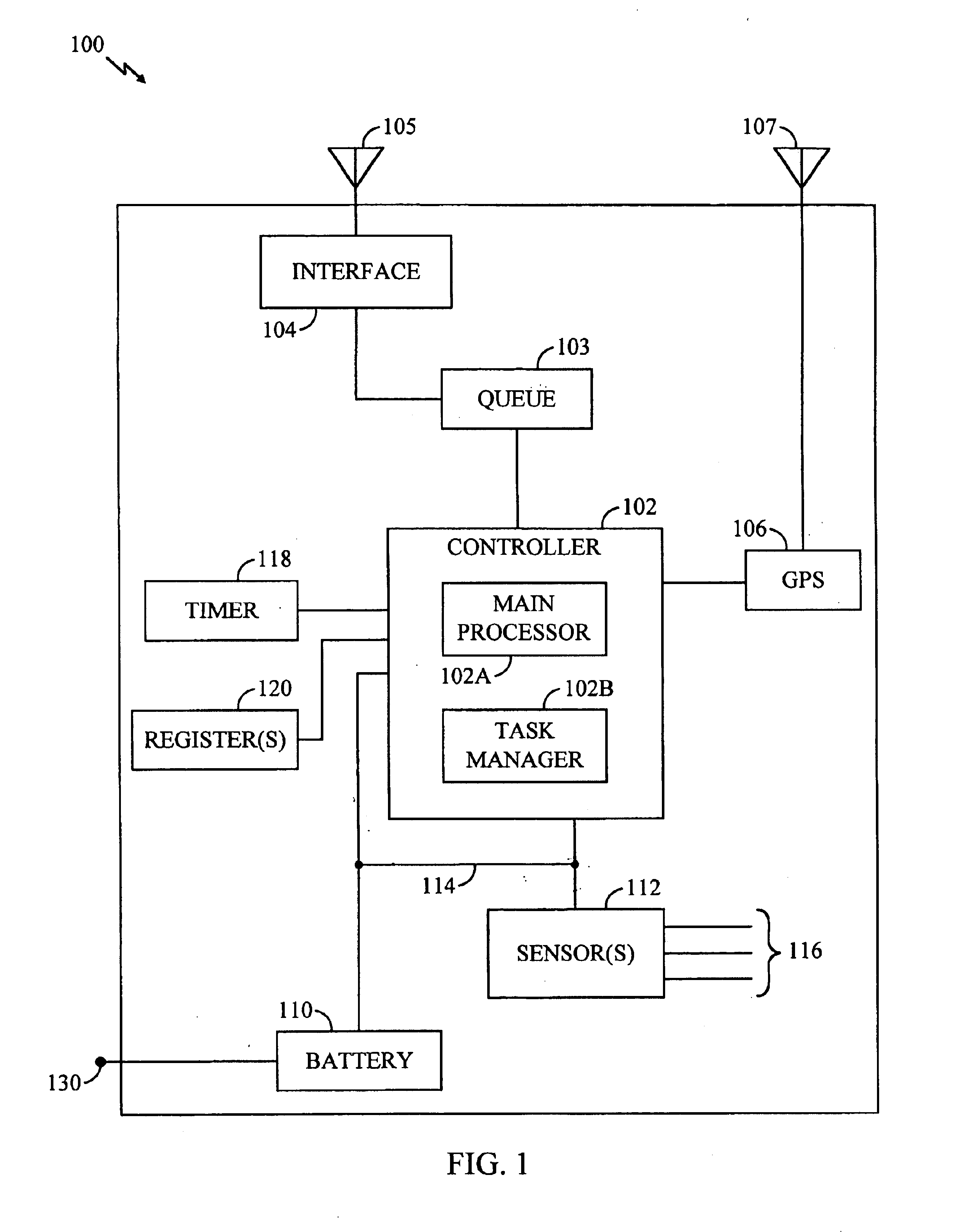
[0025]Broadly, one aspect of the invention concerns an unattended battery monitoring and management system, which transmits various status reports and manages battery powered equipment according to battery properties such as battery charge and remaining life. Although this battery monitoring equipment may be used in various applications, the present description utilizes the exemplary context of an unattended, battery-powered trailer status reporting apparatus 100, as shown in FIG. 1.

[0026]Generally, the apparatus 100 is mounted upon or inside a freight car such as a semi-tractor trailer, and serves to transmit various status reports concerning the trailer's location and condition, as explained in greater detail below. ...


PUM


Abstract

A battery monitoring apparatus that senses battery conditions such as low battery charge, end of battery capacity, and end of battery life, and responds by taking actions such as sending messages to a remote site and / or powering down. A rechargeable battery is coupled to one or more power-consuming electrical components, including battery monitoring equipment. The battery monitoring equipment senses battery charge. In response to a low-battery-charge condition, the battery monitoring equipment transmits a battery status message to a remote site and powers-down some of the electrical components. Whenever the battery nears the end of its capacity, the monitoring equipment powers down all electronic components and awaits the application of external power. The invention also tracks the time required for the battery charge to deplete. Charge duration decreases over time, and whenever it reaches a predetermined minimum, the battery monitoring equipment transmits a representative status message to the remote site.

Description

BACKGROUND OF THE INVENTION[0001]1. Field of the Invention[0002]The present invention relates to the use and charging of rechargeable batteries. More particularly, the invention concerns an unattended battery monitoring system that detects battery conditions such as low charge and impending end-of-battery-life, and responds by taking actions such as sending messages to a remote site and / or shutting down various battery-powered electrical components.[0003]2. Description of the Related Art[0004]Along with increased computing power, portability has been an important hallmark of the electronic age. Some electronic products are manufactured in handheld packages today, where the same component in past years occupied an entire room. Such portability would be meaningless without the availability of similarly portable power supplies, so it is no surprise that batteries have also undergone significant development in storage capability, compactness and other features.[0005]One especially signi...

Claims


Application Information

Patent Timeline
Patent Type & Authority Patents(United States)
IPC IPC(8): G01R31/36H02J7/00
CPCG01R31/3648H02J7/0047H02J7/0031H02J7/0048H02J7/005
Inventor DENINGER, DANIEL A.TRANDO, HUEYLOCKERMAN, MICHAELRICHARDS, ANTHONY M.PARISI, MARK D.
Owner OMNITRACS
Why Eureka
Try Eureka