Electrical connector

a technology of electrical connectors and connectors, applied in the direction of electrical apparatus, connection, coupling device connection, etc., can solve the problems of increasing manufacturing costs and sales prices, requiring extra work,

Inactive Publication Date: 2005-10-04
JAPAN AVIATION ELECTRONICS IND LTD
View PDF3 Cites 12 Cited by
  • Summary
  • Abstract
  • Description
  • Claims
  • Application Information

AI Technical Summary

Benefits of technology

[0007]It is, therefore, an object of the present invention to provide an electrical connector that connects flat type cables securely to the connector without needing extra work.

Problems solved by technology

However, in the above-described most commonly employed connections, cables need to be worked so as to be in a T-shape at the end or to be formed with holes, requiring extra work and causing the manufacturing costs and sale prices to increase.

Method used


Image

  • Electrical connector
  • Electrical connector
  • Electrical connector

Examples


Embodiment Construction

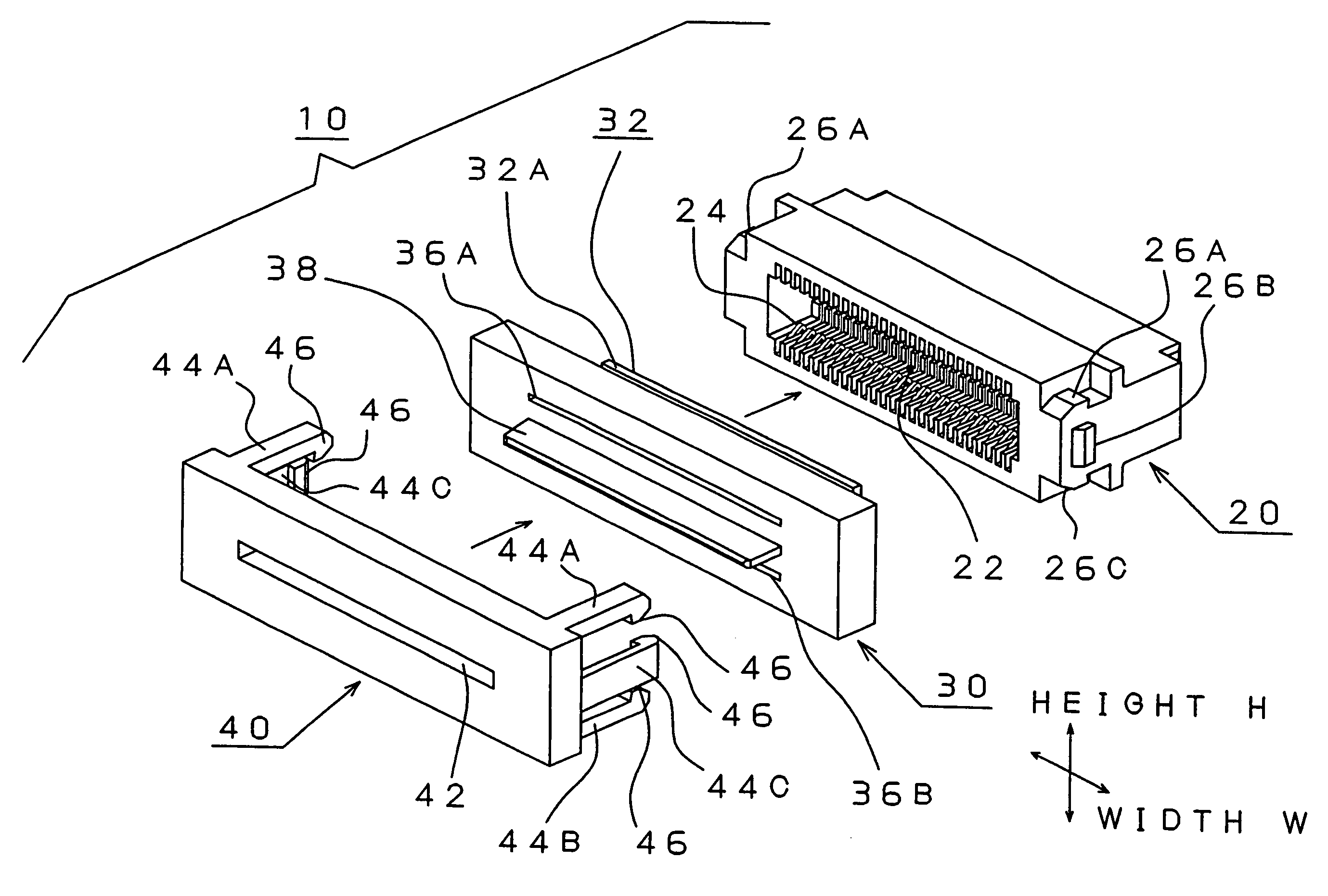
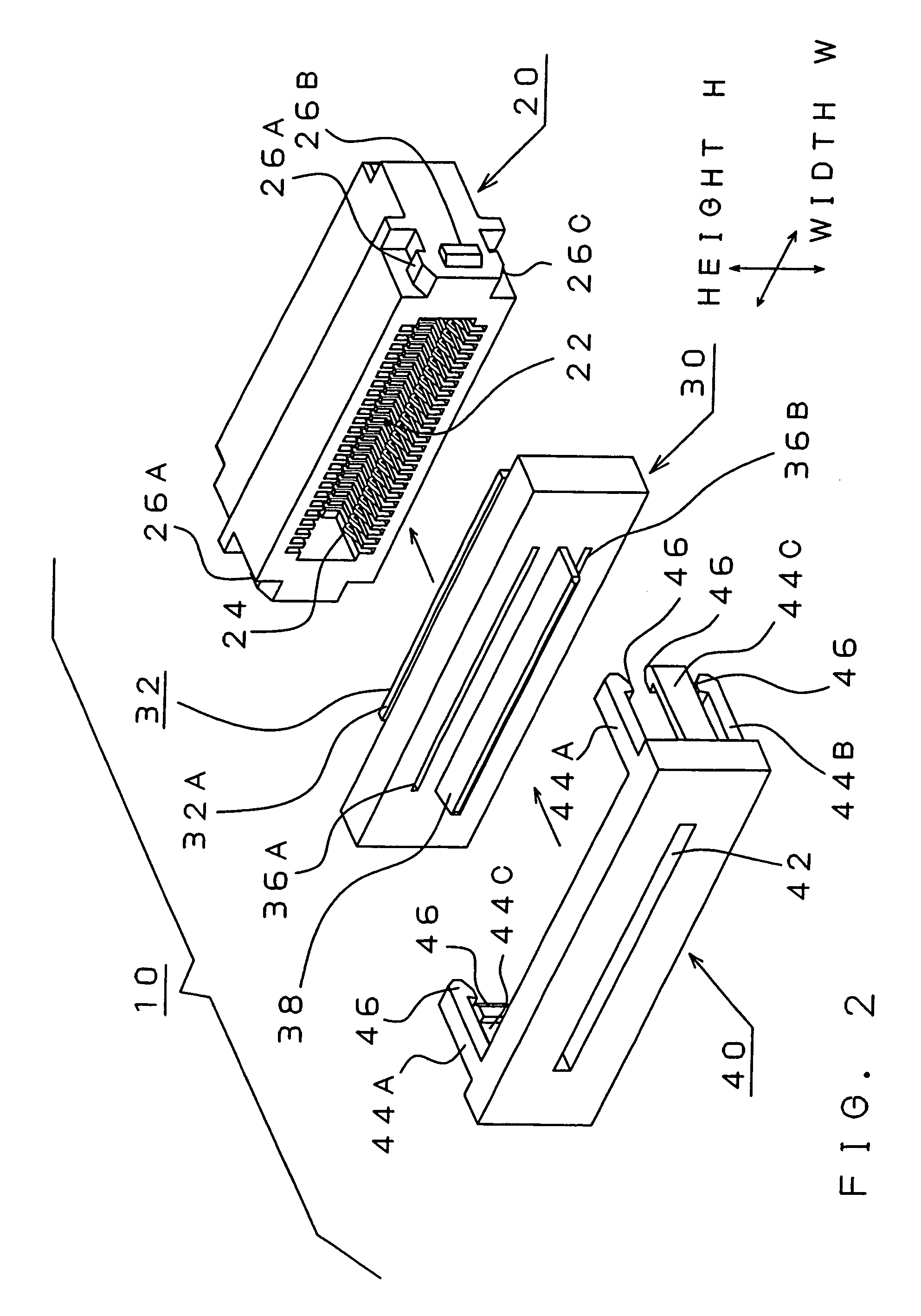
[0018]The electrical connector 10 for flat type cables of the present invention comprises: an insulating housing 20, a retaining member 30 and a holding member 40 that are made of plastic and are disengageably connected to each other to form an integral unit. The insulating housing 20, retaining member 30 and holding member 40 are substantially the same in the width (or lateral direction) W and in the height (or vertical dimension) H.

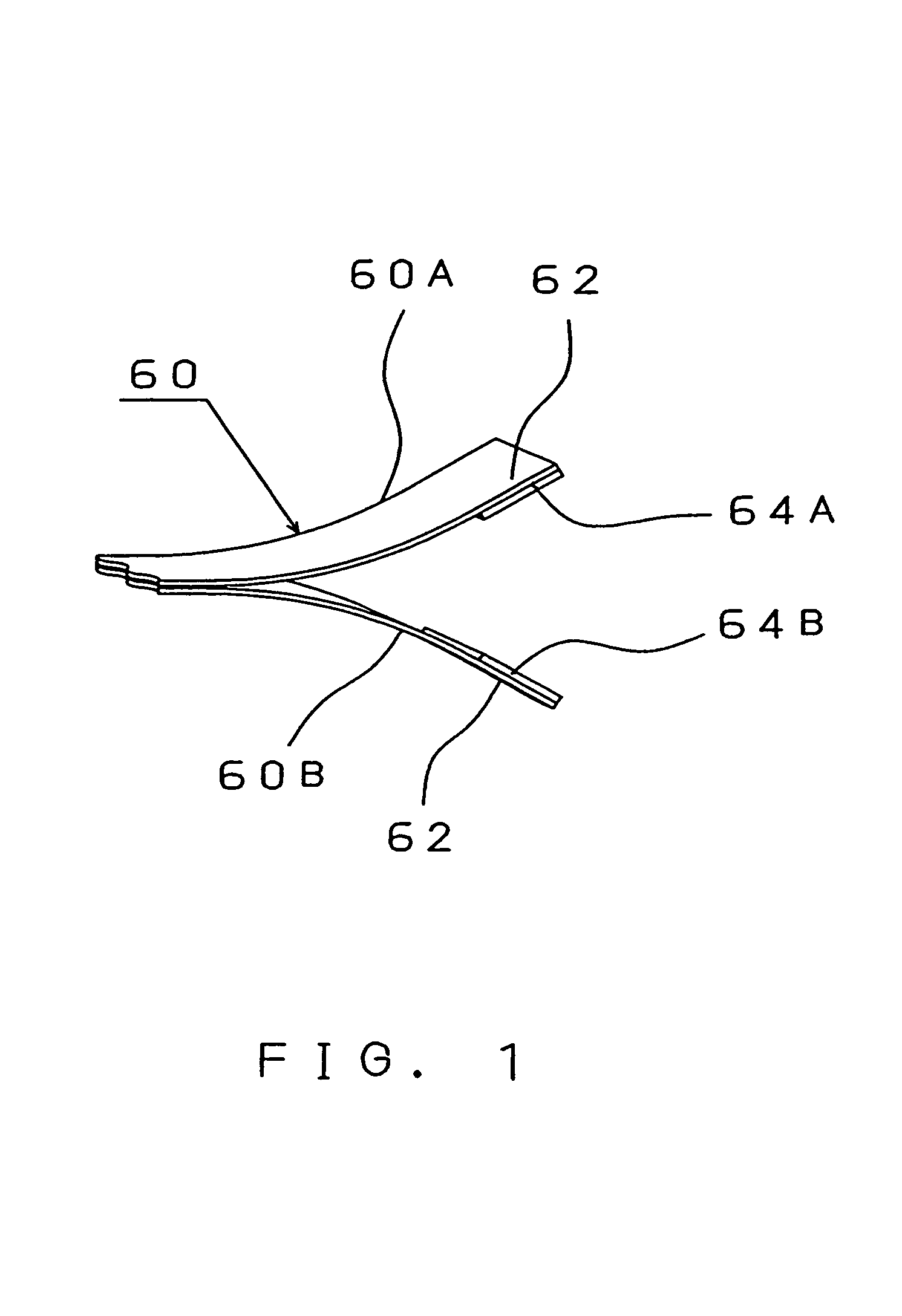
[0019]The electrical connector 10 of the present invention is used for a flat type cable (called “flat cable” or merely “cable” below) such as a flexible flat cable (“FFC”) and a flexible printed cable (“FPC”) that is, as seen from FIG. 1, a laminated cable 60 which is currently marketed and comprises a first cable element 60A and a second cable element 60B. Each one of the cable elements 60A and 60B consists of one or more flat conductors laid parallel at a specified pitch and laminated between two layers of dielectric which is typically 1 mil or 2 mil...


PUM


Abstract

An electrical connector for a flat type cable that has at its one end portion a stiff backup element, including an insulating housing having a cavity for receiving the end portion of the flat cable, a retaining member formed with a retainer block which has flat surfaces and is inserted in the cavity of the insulating housing, and a holding member engaged with the retaining member and has connecting arms that connect the holding member to the insulating housing with the retaining member in between, so that the end portion of the flat cable takes a crank shape inside the connector and the stiff backup element unbendable inside the connector prevents the cable from being pulled out of the connector.

Description

BACKGROUND OF THE INVENTION[0001]1. Filed of the Invention[0002]The present invention is related to an electrical connector and more particularly to an electrical connector for flat type cables.[0003]2. Prior Art[0004]Flat type cables such as flexible flat cables (“FFC”) and flexible printed cables (“FPC”) are widely used in electric and electronic appliances and more specifically in computers, computer peripherals and computer devices, and they are connected to such appliances via electrical connectors.[0005]The flat type cables are held by a connector in various manners. In one typical manner to connect a flat cable to a connector, the end of the cable is, as shown in FIG. 4A, shaped in letter “T”, and the both side edges of this T-shaped end are hooked to a connector. In another type of connection, as shown in FIG. 4B, the end portion of a cable is formed with holes so that the cable end is inserted into the cavity of a connector or its connector shell, and pins or spring pins, o...

Claims


Application Information

Patent Timeline
Patent Type & Authority Patents(United States)
IPC IPC(8): H01R12/24H01R12/00H01R13/58
CPCH01R13/582H01R12/774H01R12/89
Inventor SAITO, HAJIMEWATANABE, MASAHIDETODA, KENTARO
Owner JAPAN AVIATION ELECTRONICS IND LTD
Why Eureka
Try Eureka