Integrated magnetic isolated two-inductor boost converter
Inactive Publication Date: 2005-10-04
NORTHEASTERN UNIV
View PDF10 Cites 33 Cited by
- Summary
- Abstract
- Description
- Claims
- Application Information
AI Technical Summary
Benefits of technology
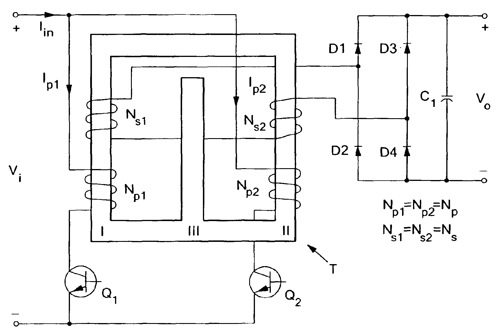
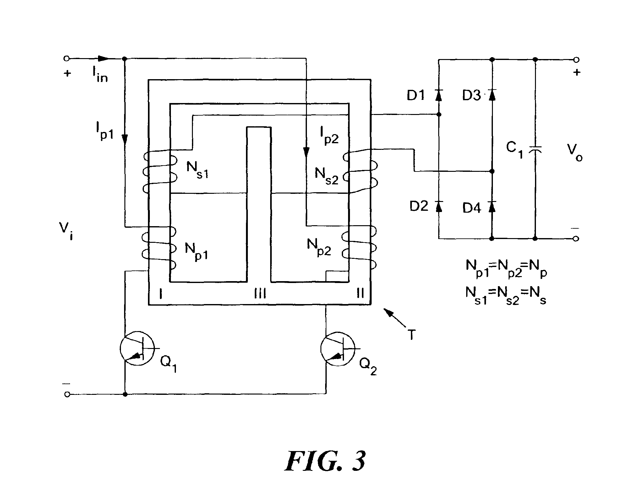
[0008]In accordance with the present invention, an isolated two-inductor boost converter employing integrated magnetics is disclosed. The converter ac
Problems solved by technology
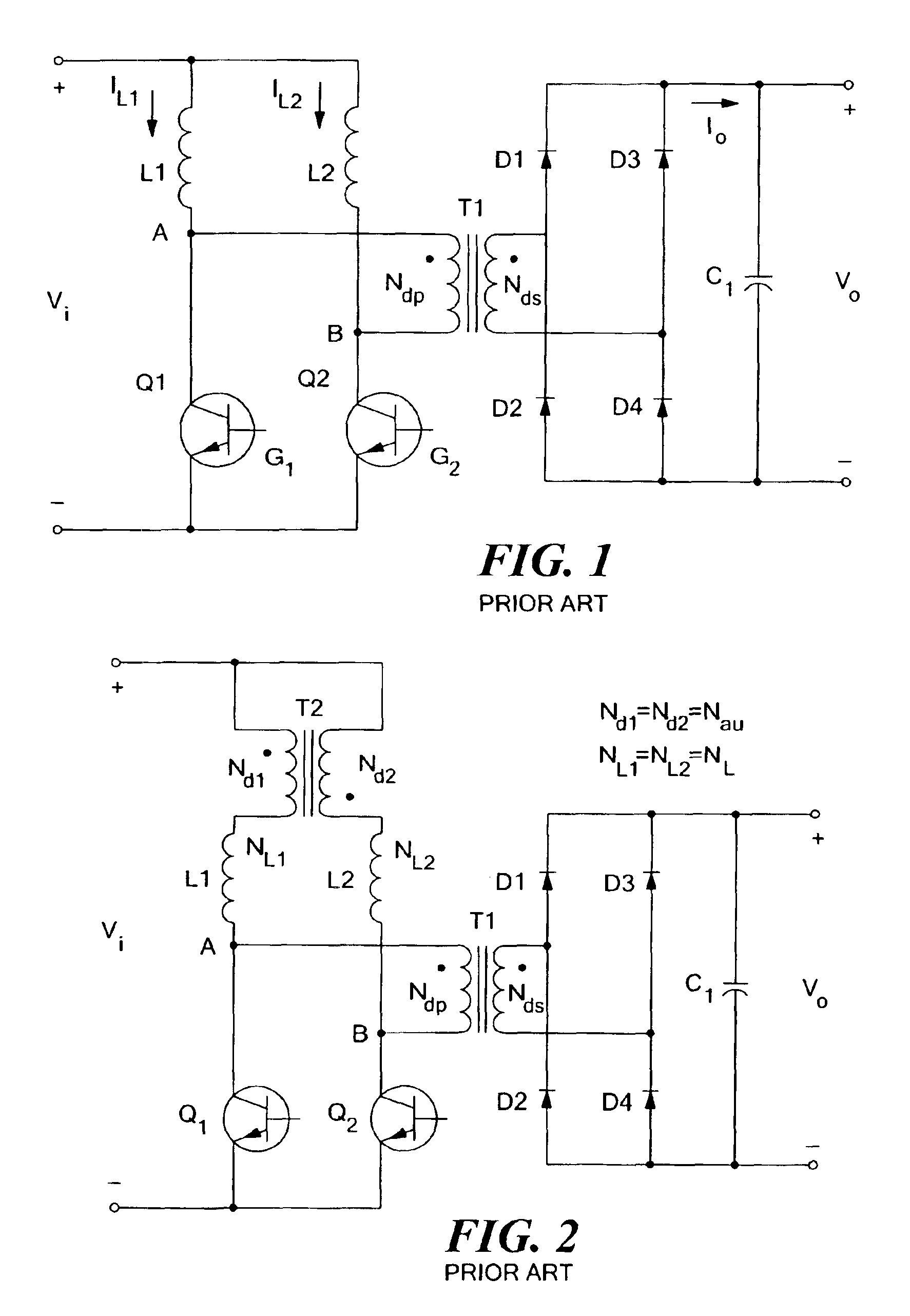
One problem with the basic two-inductor boost converter topology is its limited power regulation range.
If the load demands less power than this minimum level, the output voltage increases abnormally because ex
Method used
View moreImage
Smart ImageViewing Examples
Examples
 PUM
 Abstract
A two-inductor boost converter includes an integrated magnetic core having a three-legged flux-conducting element with an energy-storing gap, for example in the center leg. Two primary windings are disposed on respective legs, such as the outer legs, and are coupled in parallel to one input terminal of the converter. Two series-connected secondary windings are also disposed on the flux-conducting element, and are connected to rectification and filtering circuitry which may have full bridge, full wave, or voltage doubler configuration. Primary-side switches are coupled in series between each primary winding and the other converter input terminal. Control circuitry generates control signals for the primary-side switches, providing for a desired degree of overlapped conduction during each operating cycle along with periods of non-conduction that result in transferring electrical energy to the load. The integrated magnetic core can include additional windings for ancillary functions, such as for flyback operation during start-up.
Description
CROSS REFERENCE TO RELATED APPLICATIONS[0001]This application claims priority under 35 U.S.C. §119(e) of U.S. Provisional Patent Application No. 60 / 444,821 filed Feb. 4, 2003, the disclosure of which is hereby incorporated by reference herein.STATEMENT REGARDING FEDERALLY SPONSORED RESEARCH OR DEVELOPMENT[0002]Not ApplicableBACKGROUND OF THE INVENTION[0003]The present invention is related to the field of DC—DC power converters.[0004]Among the myriad types of circuit topologies employed in DC—DC power converters is a converter known as the “two-inductor boost converter”. This converter has a boost, or voltage-step-up, transfer function, and employs two parallel inductors with partially overlapped conduction. The two-inductor boost converter exhibits benefits particularly in high power applications due to the splitting of high input current between two inductors and the resulting reduction in I2R power loss in both copper windings and primary-side switches. An interleaving control str...
Claims
Login to View More Application Information
Patent Timeline
 IPC IPC(8): H02M3/337H02M3/24
CPCH02M3/3372
Inventor YAN, LIANGLEHMAN, BRADLEY M.
Owner NORTHEASTERN UNIV
Features
- R&D
- Intellectual Property
- Life Sciences
- Materials
- Tech Scout
- Unparalleled Data Quality
- Higher Quality Content
- 60% Fewer Hallucinations
Learn More Browse by: Latest US Patents, China's latest patents, Technical Efficacy Thesaurus, Application Domain, Technology Topic, Popular Technical Reports.
© 2025 PatSnap. All rights reserved.Legal|Privacy policy|Modern Slavery Act Transparency Statement|Sitemap|About US| Contact US: help@patsnap.com


