Partition mount

a technology of partition mounts and mounting brackets, applied in the direction of curtain suspension devices, door/window protective devices, machine supports, etc., can solve the problems of damage to their surfaces, design suffers from several limitations, tape usually fails to stick, etc., and achieves the effect of installing and removing

Inactive Publication Date: 2005-10-11
ZIPWALL
View PDF129 Cites 52 Cited by
  • Summary
  • Abstract
  • Description
  • Claims
  • Application Information

AI Technical Summary

Benefits of technology

[0007]The present invention is directed to a partition mount apparatus and method which overcome the limitations of the prior art. The inventive method and apparatus are applicable to use in construction zones in preventing contaminants such as dust and paint from entering clean areas in a home or office. The invention may also be used as a temporary visual, odor, or sound barrier, depending on the curtain material employed. The present invention offers the advantages of accommodating standard extension poles, for example, painters poles, with standard threads, and is compatible with a variety of commercially-available curtain or drape materials, for example plastic, cloth, or the like. The invention is a “clean” system designed to be installed and removed without damaging or otherwise marking the ceiling, floor or walls in the construction zone. Assembly is easy and fast and can be accomplished by a single individual. In a preferred method for assembling the partition of the present invention, the curtain mounts and curtain are first assembled on the floor and then raised to the ceiling permitting safe installation in rooms with high ceilings, for example cathedral ceilings.
[0008]One embodiment of the invention comprises a spring-loaded mount including a hole at a proximal end, a compression mechanism, and a head at a distal end. The hole is adapted to receive the end of a standard length-adjustable pole or painters pole. In a preferred embodiment, the compressive mechanism comprises a spring under compression between an inner wall of the mount and the head. The head is urged toward the ceiling by the compressive mechanism, providing longitudinal rigidity to the installed mount. The head preferably interfaces with the mount at a swivel joint so that the mount can be installed at a range of orientations relative to the ceiling.
[0009]The head preferably includes a coupling device, for example, a Velcro™ hook and loop fastener strip, a hook, or a clip, adapted to receive a portion of a curtain. In a first preferred embodiment of the invention, the face of the head includes a sheet of Velcro™ hooks which mates with a sheet of Velcro™ loops attached to the curtain. On the side of the curtain opposite the Velcro™ loops, a high-friction material provides friction between the mount and the ceiling, so that the curtain is less likely to slide relative to the ceiling thereby providing lateral rigidity.
[0010]In a second preferred embodiment of the invention, a removable clip couples the curtain to the head. The clip is adapted to receive a section of curtain material and snap on or otherwise secure to the head. High friction material attached to the back of the clip provides lateral rigidity as described above.
[0012]In the inventive method of the present invention, a spring-loaded curtain mount is coupled to the end of a standard adjustable pole, and the length of the pole is adjusted such that the combined length of the pole and mount is slightly longer than the distance between the floor and ceiling. A portion of the curtain is attached to the curtain mount. The curtain and mount are raised to the ceiling and the mount and pole are compressed between and the floor and ceiling. This compressive force operates to urge the head toward the ceiling. The same compressive force operating through the high friction material on the head or curtain provides lateral rigidity for the system.
[0013]The mount is free-standing and therefore does not require additional “destructive” mounting means, for example nailing or taping. Instead, the mount is installed and removed without permanent damage to the ceiling or floor.

Problems solved by technology

Some simply nail, screw, or staple the curtain or partition material to the floor, ceiling, and abutting walls, resulting in damage to their surfaces.
The tape usually fails to stick, but if it does stick, as the tape is removed, paint usually pulls off with the tape or adhesive is left behind.
This design suffers from several limitations.
The support poles, header elements, fasteners, and curtain all comprise dedicated hardware, increasing manufacturing costs.
In addition, installation appears to be awkward and time consuming due to the multitude of fasteners and the system appears to be top-heavy during installation.
The structure is bulky and appears tedious to install.
Although this design accommodates any type of curtain material, it again suffers from the limitation of requiring dedicated hardware as the support member is designed for a particular extension pole.
In addition, installation appears challenging in rooms with tall ceilings as the curtain is installed after the mount is raised and installed.
In a home construction project, the snapping action may damage the ceiling.
In addition, for ceilings higher than the reach of the installer, this design may prove to be challenging to install.
This design presents the further unfortunate possibility that the installer could jam his fingers between the support member and ceiling.

Method used


Image

  • Partition mount
  • Partition mount
  • Partition mount

Examples


Embodiment Construction

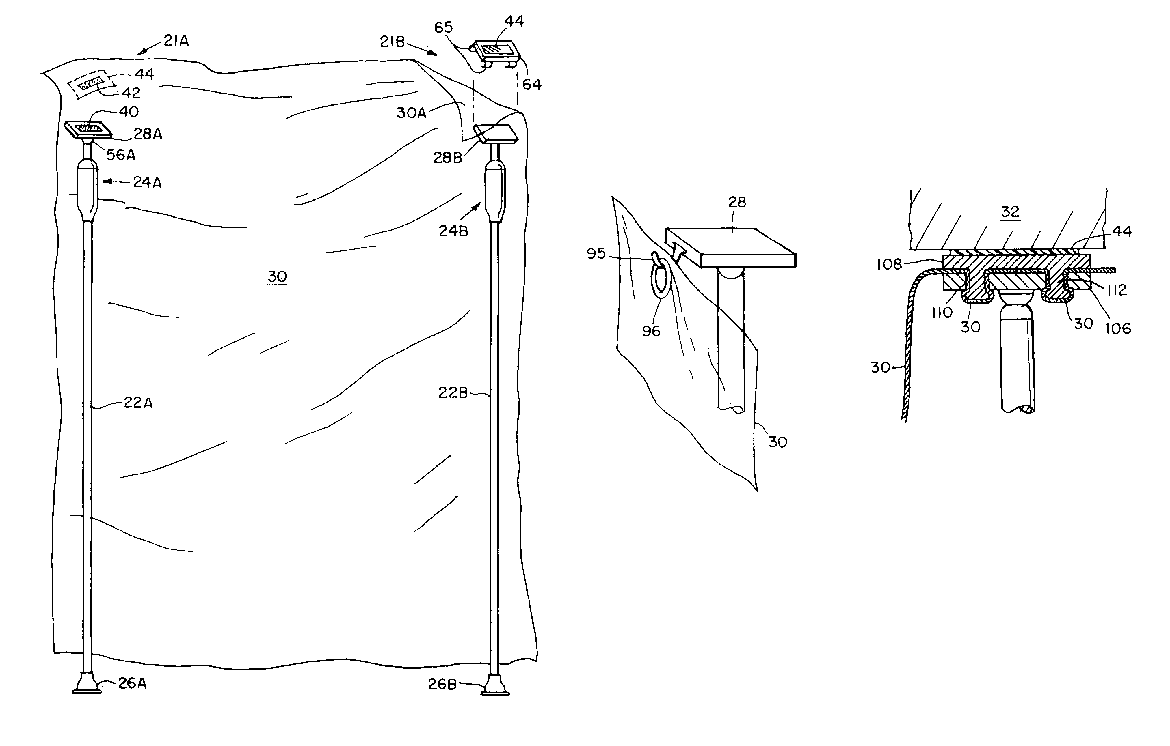
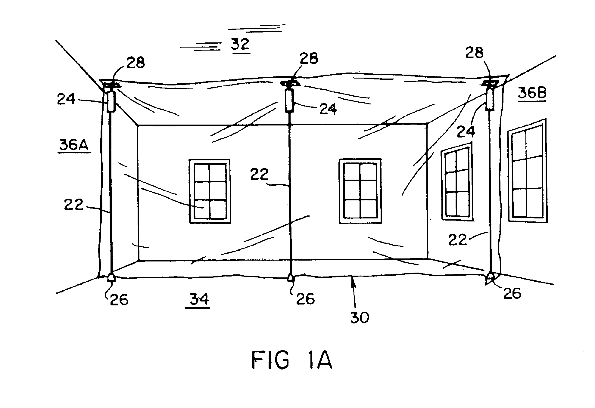
[0030]FIG. 1A illustrates an installed partition extending from the floor 34 to the ceiling 32 of a room between opposed walls 36A, 36B. Three curtain mounts 24 in accordance with the present invention are mounted on extension poles 22. A foot 26 at the bottom of each extension pole interfaces with the floor and a head 28 at the top of each curtain mount interfaces with the ceiling 32. The contact or interface points of the foot and head preferably are covered with a soft friction material such as rubber to provide lateral rigidity of the system and to prevent marking of the ceiling and floor.

[0031]Each curtain mount includes a compression mechanism, for example a spring, which operates to urge the head 28 against the ceiling 32, thereby securing the curtain 30. The extension poles 22 are preferably adjustable such that before installation of the curtain 30, the pole length in combination with the fully extended curtain mount 24 can be made slightly larger than the distance from the...


PUM


Abstract

In a spring-loaded curtain mount, the mount includes a pole interface at a proximal end, a compressive mechanism, and a head at a distal end. The pole interface is adapted to receive the end of a standard length adjustable pole or a painter's pole. The compression mechanism is disposed between the proximal end of the mount and the head. The mount includes a coupling device adapted to receive a portion of a curtain. During installation, the curtain mount is coupled to the end of an extension pole and the length of the pole is adjusted such that the combined length of the pole and mount is slightly longer than the distance between the floor and ceiling. At ground level, a portion of the curtain is attached to the head of the curtain mount. The curtain and mount are raised to the ceiling and the mount and pole are compressed between the floor and the ceiling. This compressive force operates to urge the head toward the ceiling, securing the mount in place.

Description

RELATED APPLICATIONS[0001]This application is a continuation of U.S. application Ser. No. 10 / 301,233, filed Nov. 21, 2002, which is a continuation application of U.S. application Ser. No. 09 / 884,337, filed Jun. 19, 2001, now U.S. Pat. No. 6,508,295 which is a continuation of U.S. application Ser. No. 09 / 613,645, filed Jul. 11, 2000, now U.S. Pat. No. 6,321,823, which is a continuation of U.S. application Ser. No. 09 / 302,122, filed Apr. 29, 1999, now U.S. Pat. No. 6,209,615, which is a continuation of U.S. application Ser. No. 08 / 740,372, filed Oct. 29, 1996, now U.S. Pat. No. 5,924,469, the contents of the applications being incorporated herein by reference.BACKGROUND OF THE INVENTION[0002]Partition systems are often employed to separate portions of a building or room. Partitions serve as a barrier to dust, noise, light, odors, and the like. In construction zones, partitions are useful for protecting a clean area from a work area, for example, protecting an area where furniture and ...

Claims


Application Information

Patent Timeline
Patent Type & Authority Patents(United States)
IPC IPC(8): E04G21/24A47H1/00
CPCA47H21/00E04G21/243E04G21/30E04G21/24Y10T24/4406Y10T24/3672Y10T24/44923A47H2201/02Y10T24/3606Y10S52/12E04G2021/248E04G2025/006E04G2025/047
Inventor WHITTEMORE, JEFFREY P.
Owner ZIPWALL
Why Eureka
Try Eureka