Partially Retrievable Safety Valve

Active Publication Date: 2012-08-09
SAUDI ARABIAN OIL CO
View PDF6 Cites 11 Cited by
  • Summary
  • Abstract
  • Description
  • Claims
  • Application Information

AI Technical Summary

Benefits of technology

[0013]The present concept provides for a very reliable means for a safety valve, allowing the actuator system to be removed and redressed periodically with the ESP during routine rigless replacement of the actuator system and ESP. The system can be installed and removed without a rig.
[0014]The current application provides a solution where there is no need or opportunity to open the valve if the ESP

Problems solved by technology

But that method can cause formation damage so it is therefore more desirable to control the well than to kill it.
Normally deep-set safety valves are controlled via a single ¼″ OD hydraulic umbilical to the surface, but at deep depths, the hydraulic pressures are very high and even when the hydraulic system fails, the magnitude of residual hydraulic pressure can be significant.
There will also come a point when the hydraulic pressures would be so great that a spring system would become very difficult to implement and eventually become unfeasible.
Also, a typical failure mode of most flapper-ty

Method used


Image

  • Partially Retrievable Safety Valve
  • Partially Retrievable Safety Valve
  • Partially Retrievable Safety Valve

Examples


Embodiment Construction

Embodiments of the Present System and Method Include

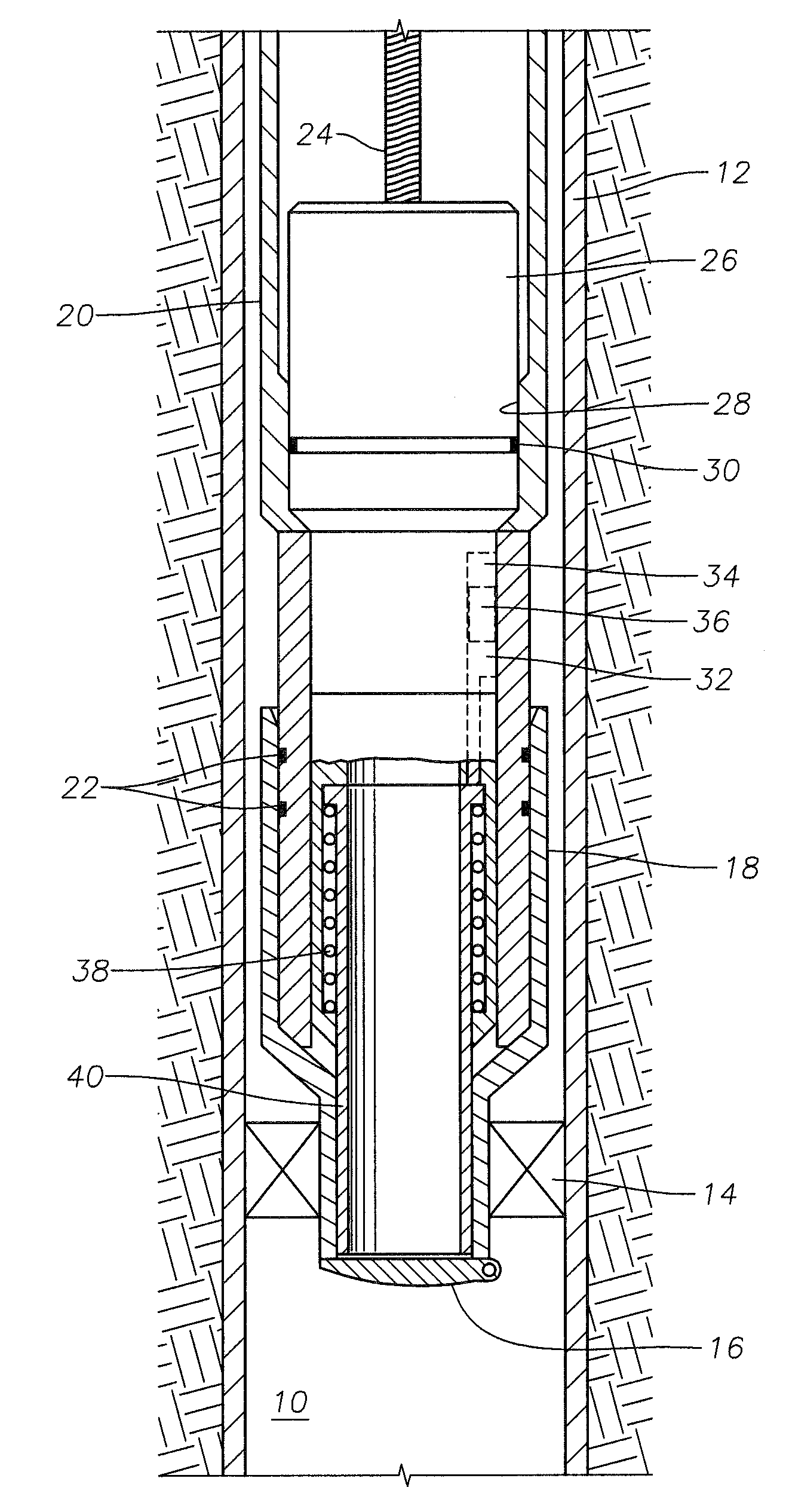
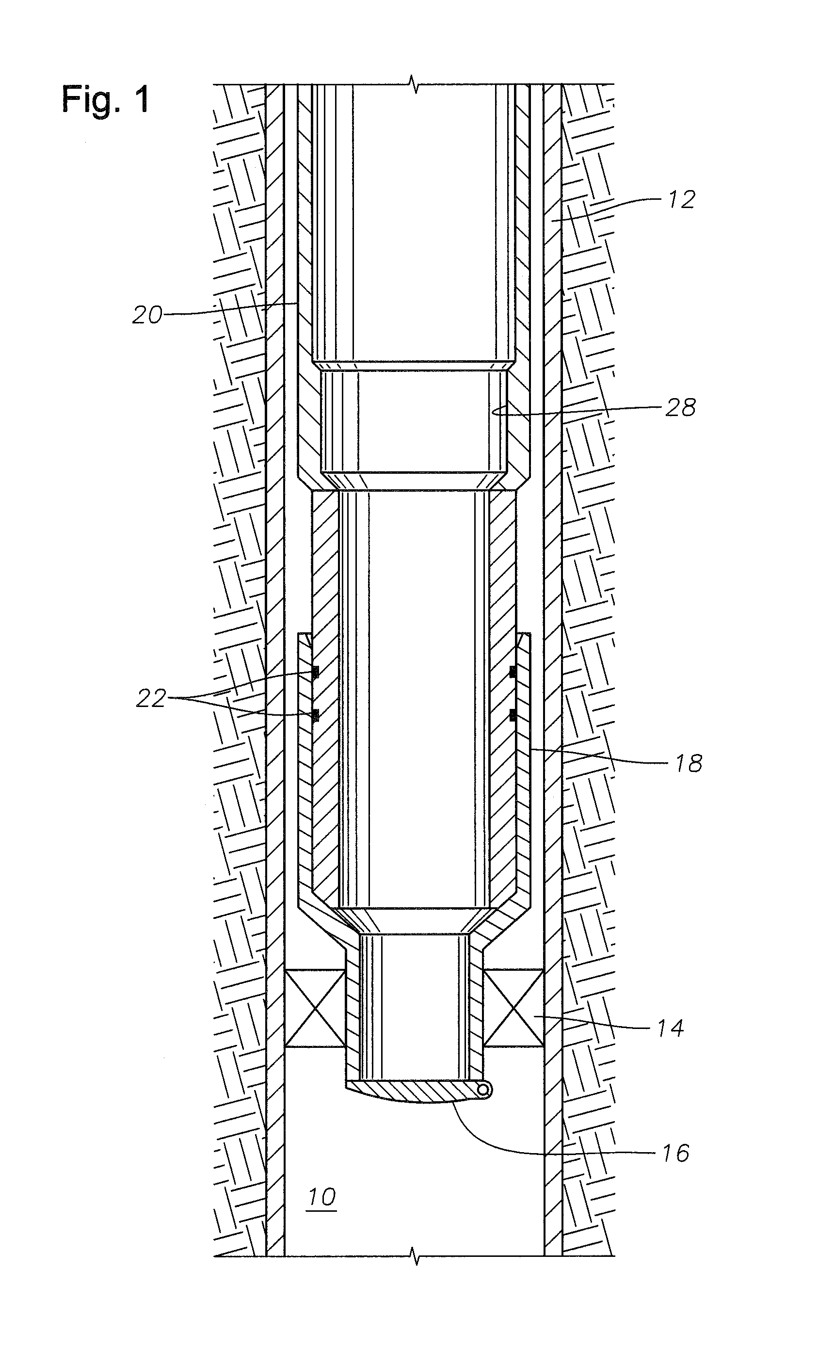
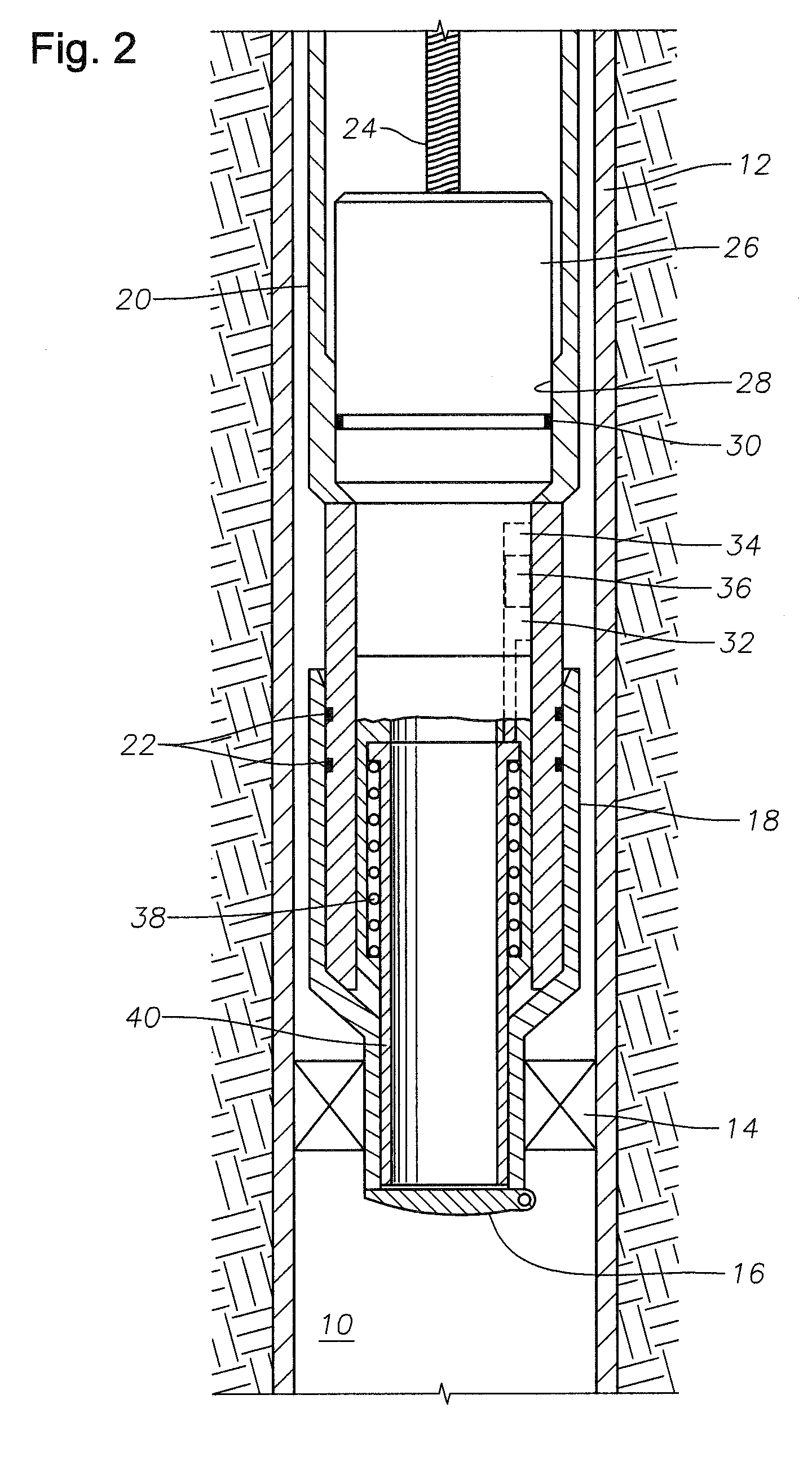
[0032]As seen in FIG. 1, the system may be employed in a cased well 10 with casing 12. Components installed in such a well 10 may include a packer 14 with integral valve 16. Valve 16 is shown as a flapper valve but may alternatively be any valve in the generic globe valve family. A globe valve may be, for example, a butterfly valve, a gate valve or a ball valve. Packer 14 has a polished bore receptacle 18 at its upper end. A tubing string 20 is connected to the polished bore receptacle 18. This connection may be made as the tubing string 20, which has a lower outer diameter slightly smaller than the inner diameter of the polished bore receptacle 18, comes into sliding engagement with the polished bore receptacle 18 as the tubing string 20 is lowered into the well 10. The bottom of tubing string 20 has a reduced diameter compared to the upper portion of the tubing string 20, to allow for this sliding engagement with the polished bor...


PUM


Abstract

A method, system and apparatus is provided for a partially retrievable safety valve to control a well. The method includes securing a normally closed valve in the well. The valve may be a self-equalizing flapper valve. Following this, an actuator system operable to open the valve is run into the well. The actuator system is removable from the well while the valve remains closed and secured in the well. A submersible pump and motor may be secured to the actuator system before the actuator system is run into the well. The submersible pump and motor are also removable from the well while the valve remains closed and secured in the well. Therefore the actuator system, submersible pump and motor can be replaced or redressed, while the valve remains closed, keeping the well under control at all times.

Description

BACKGROUND OF THE INVENTION[0001]1. Area of the Invention[0002]The present invention relates to deep-set safety valves used in subterranean well production. More specifically, the present invention relates to deep-set safety valves used in connection with submersible pumps for controlling a well.[0003]2. Description of the Related Art[0004]In subsurface wells, such as oil wells, an electrical submersible pump with a motor (an “ESP”) is often used to provide an efficient form of artificial lift to assist with lifting the production fluid to the surface. ESPs decrease the pressure at the bottom of the well, allowing for more production fluid to be produced to the surface than would otherwise be produced if only the natural pressures within the well were utilized.[0005]There may be times when an operator of a well would want or need to retrieve an ESP from within the well. In order to do so, the operator must have a means for closing off the well so that the production fluid does not s...

Claims


Application Information

Patent Timeline
IPC IPC(8): E21B34/10E21B34/16
CPCE21B34/107E21B2034/005E21B43/128E21B41/00E21B2200/05
Inventor BOULDIN, BRETT WAYNESMITH, STEPHEN WAYLAND
Owner SAUDI ARABIAN OIL CO
Why Eureka
Try Eureka