Quick install/remove stove guard

a stove guard and installation procedure technology, applied in the field of quick installation/removal of stove guards, can solve the problems of complex installation procedures, difficult cleaning of devices, and heat damage to the guard panel, and achieve the effect of reliable and simple, minimizing the chance of heat damag

a stove guard and installation procedure technology, applied in the field of quick installation/removal of stove guards, can solve the problems of complex installation procedures, difficult cleaning of devices, and heat damage to the guard panel, and achieve the effect of reliable and simple, minimizing the chance of heat damag

US20080135036A1Inactive Publication Date: 2008-06-12DANG QI

Image

  • Quick install/remove stove guard
  • Quick install/remove stove guard
  • Quick install/remove stove guard

Examples


Embodiment Construction

[0019]The invention provides a new and improved design of the stove guard. For the purposes of promoting an understanding of the principles of the invention, reference will now be made to the embodiments illustrated in the drawings referring to FIGS. 1 to 7.

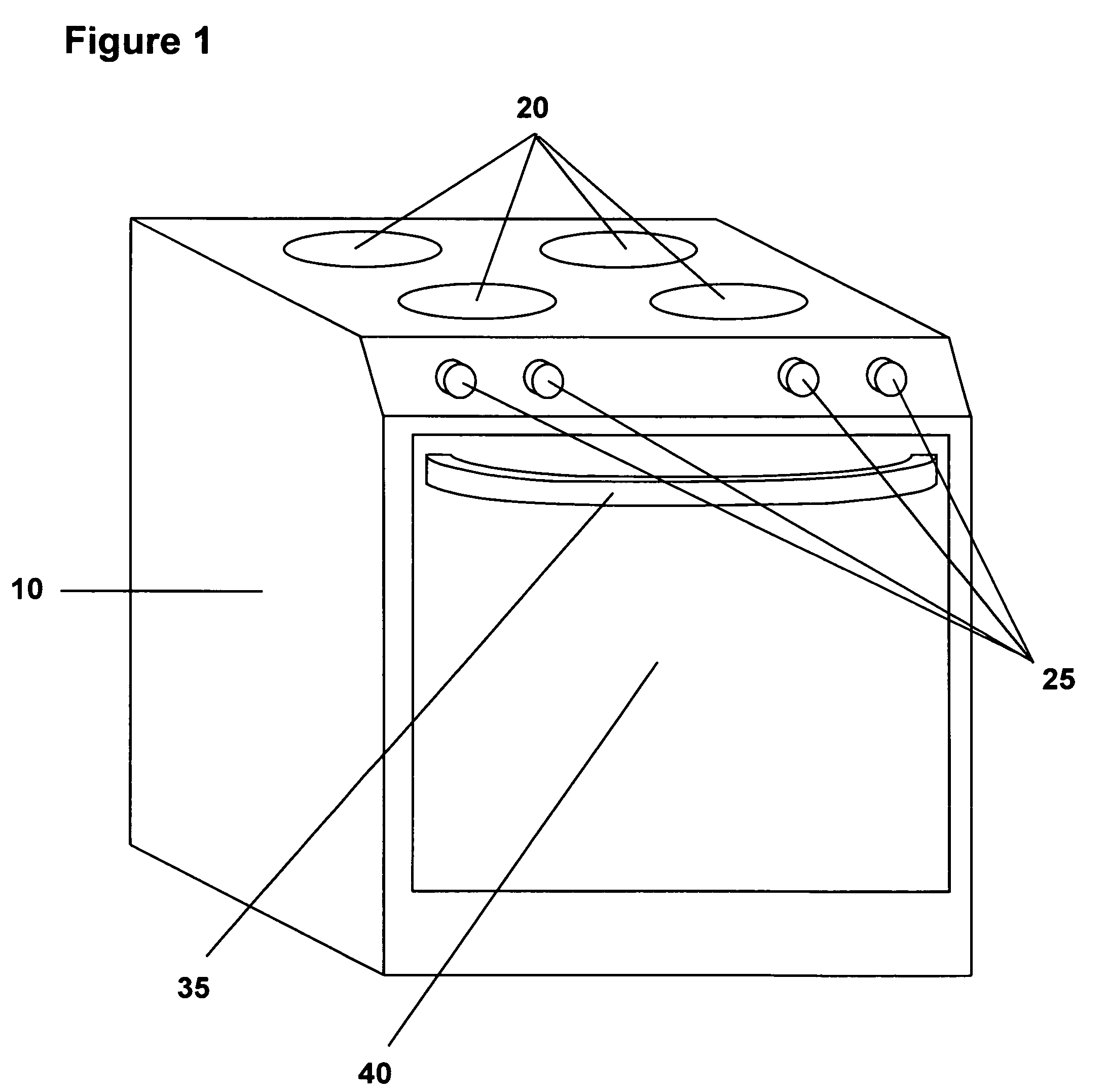
[0020]FIG. 1 is a view of a typical range 10. Burners 20 are located on the top of the range 10. Control knobs 25 are located in the upper front of the range. The oven is located beneath the burner top. A hinged oven door 40 is located in the front of the oven. An elongated C-shaped oven door handle 35 is attached to the upper portion of the oven door.

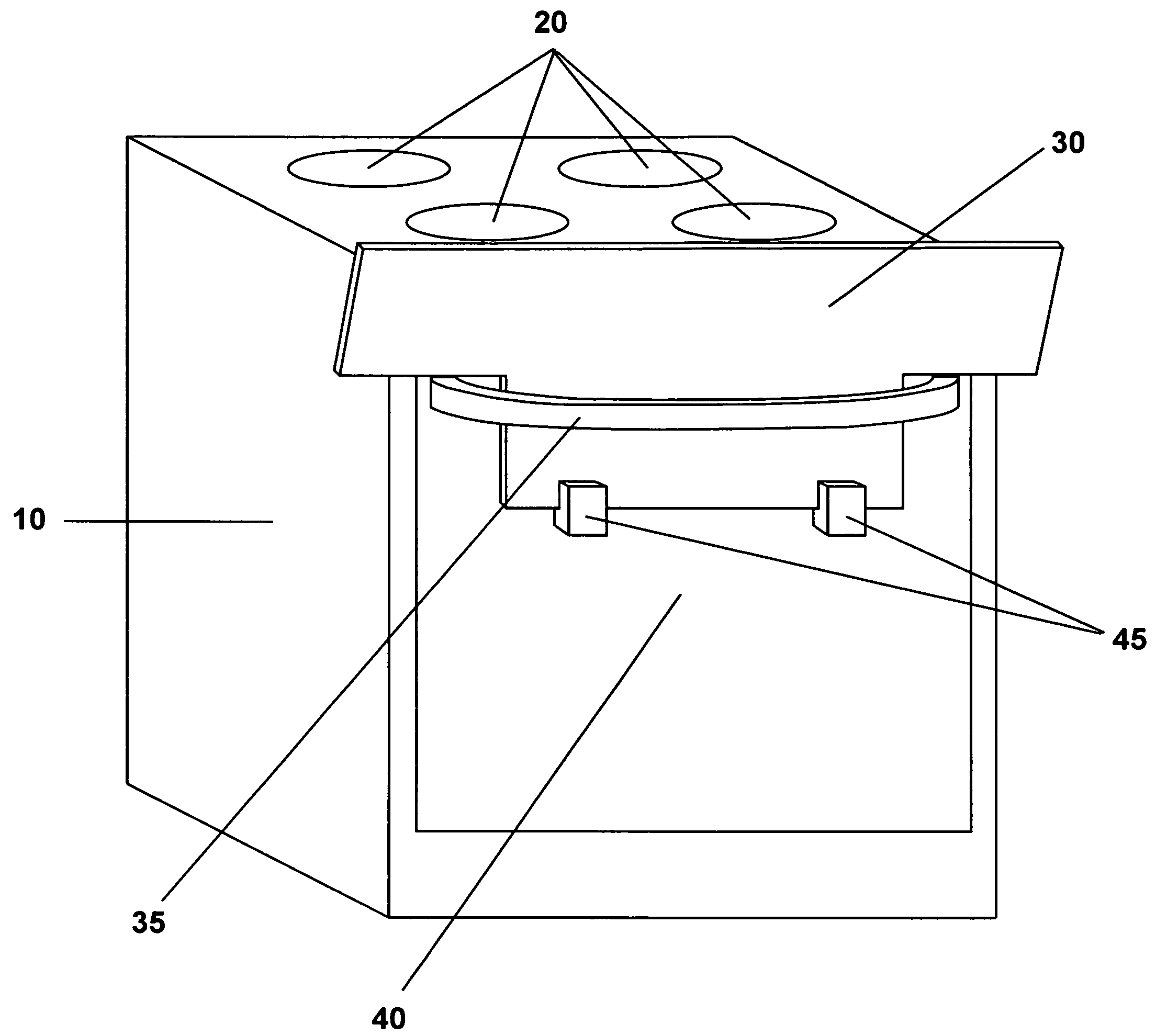
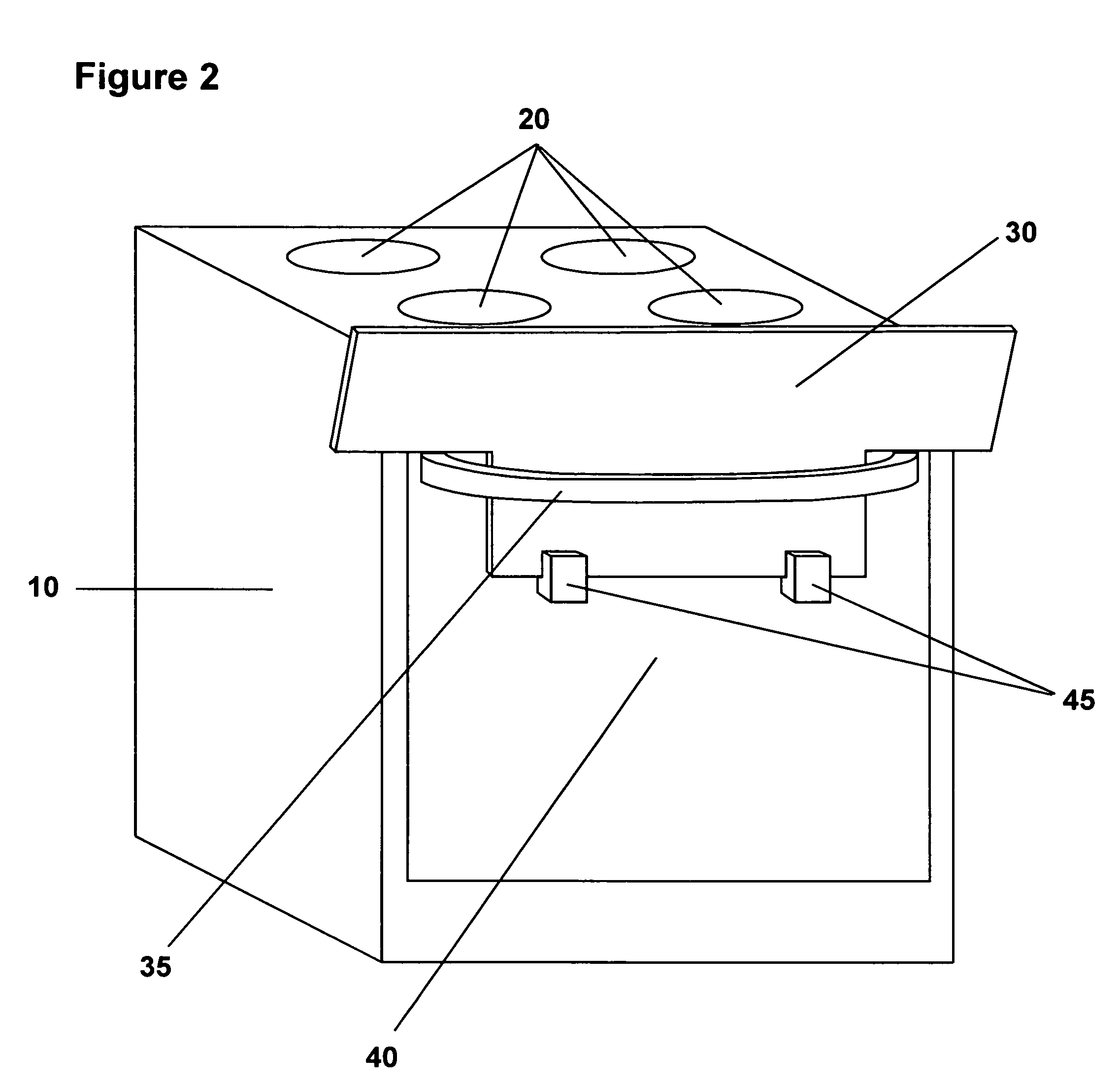
[0021]FIG. 2 is the perspective view of the range with the stove guard panel 30 inserted and secured into position by holding devices 45. The width of the lower portion of the guard panel is reduced and inserted between the oven door handle 35 and the oven door. The bottom edge of the guard panel is secured by inserting the bottom edge into the deep groove 47 on the upper portion of...


PUM


Abstract

A stove (or range) burner guard attached to the front of a gas or electrical stove (or range) by inserting the lower portion of the guard between the oven door handle and the oven door. The guard is secured by two identical holding devices, which are attached to the surface of the oven door. The guard prevents young children from reaching the burners, control knobs and cookware on the stovetop. The guard can be installed or removed in seconds.

Description

CROSS REFERENCE TO RELATED APPLICATIONS[0001]Not ApplicableSTATEMENT REGARDING FEDERALLY SPONSORED RESEARCH OR DEVELOPMENT[0002]Not ApplicableDESCRIPTION OF ATTACHED APPENDIX[0003]Not ApplicableBACKGROUND OF THE INVENTION[0004]1. Field of invention[0005]The invention is related to a quick install / remove stove burner guard, which prevents small children from reaching the burners, control knobs and cookware on the stovetop. The guard also prevents small children from coming in contact with heated liquid or other foods that may bubble or splash from cookware on the stovetop. The guard panel can be installed or removed in seconds.[0006]2. Description of the Prior Art[0007]A number of stove guards were invented in the prior art to prevent small children from reaching the stove burners, control knobs and cookware while cooking as listed on the following list:4157705June 1979Caan4517955May 1985Ehrlich et al.4836181June 1989Saga5546928August 1996Lewis et al.5758636June 1998Butrimas et al.58...

Claims


Application Information

Patent Timeline
12 Jun 2008
Publication
US20080135036A1
IPC
F24C15/36
CPC
F24C15/36
Inventors
DANG, QI