Pyrotechnic safety element

a safety element and pyrotechnic technology, applied in the direction of battery cutoff switch, circuit severing switch, electrical apparatus, etc., can solve the problem of comparatively unproblematic licensing of fuse elements, and achieve the effect of easy and cost-efficient manufacturing

Inactive Publication Date: 2005-10-11
LELL PETER
View PDF11 Cites 11 Cited by
  • Summary
  • Abstract
  • Description
  • Claims
  • Application Information

AI Technical Summary

Benefits of technology

The invention provides a pyrotechnic fuse element that can be used in a cost-efficient and easy way. This fuse element can have both a self-triggering function and a controllable triggering function.

Problems solved by technology

The technical problem addressed in this patent text is the development of a reliable and safe fuse element for automotive engineering that can be triggered in a controllable manner and can be used as a safety fuse without the need for a detonative explosive. The fuse element should also have a high-current carrying capacity and should be able to withstand hot gas and plasma without causing danger. Additionally, the fuse element should ideally be able to separate the circuit quickly in case of an emergency without the need for a detonative explosive.

Method used


Image

  • Pyrotechnic safety element
  • Pyrotechnic safety element
  • Pyrotechnic safety element

Examples


Embodiment Construction

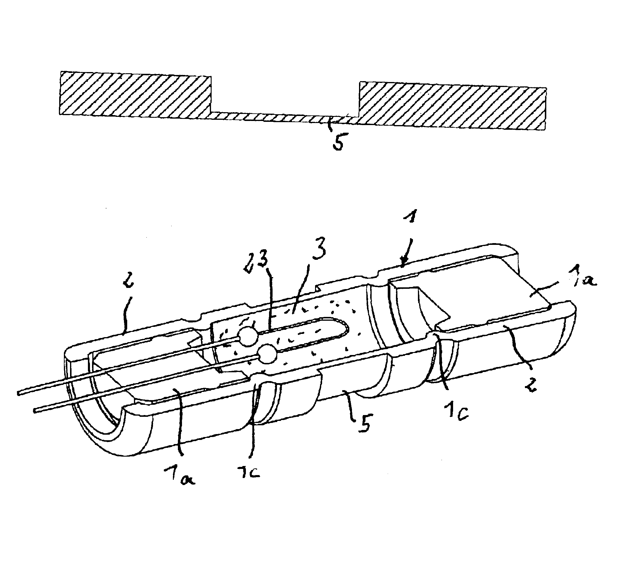
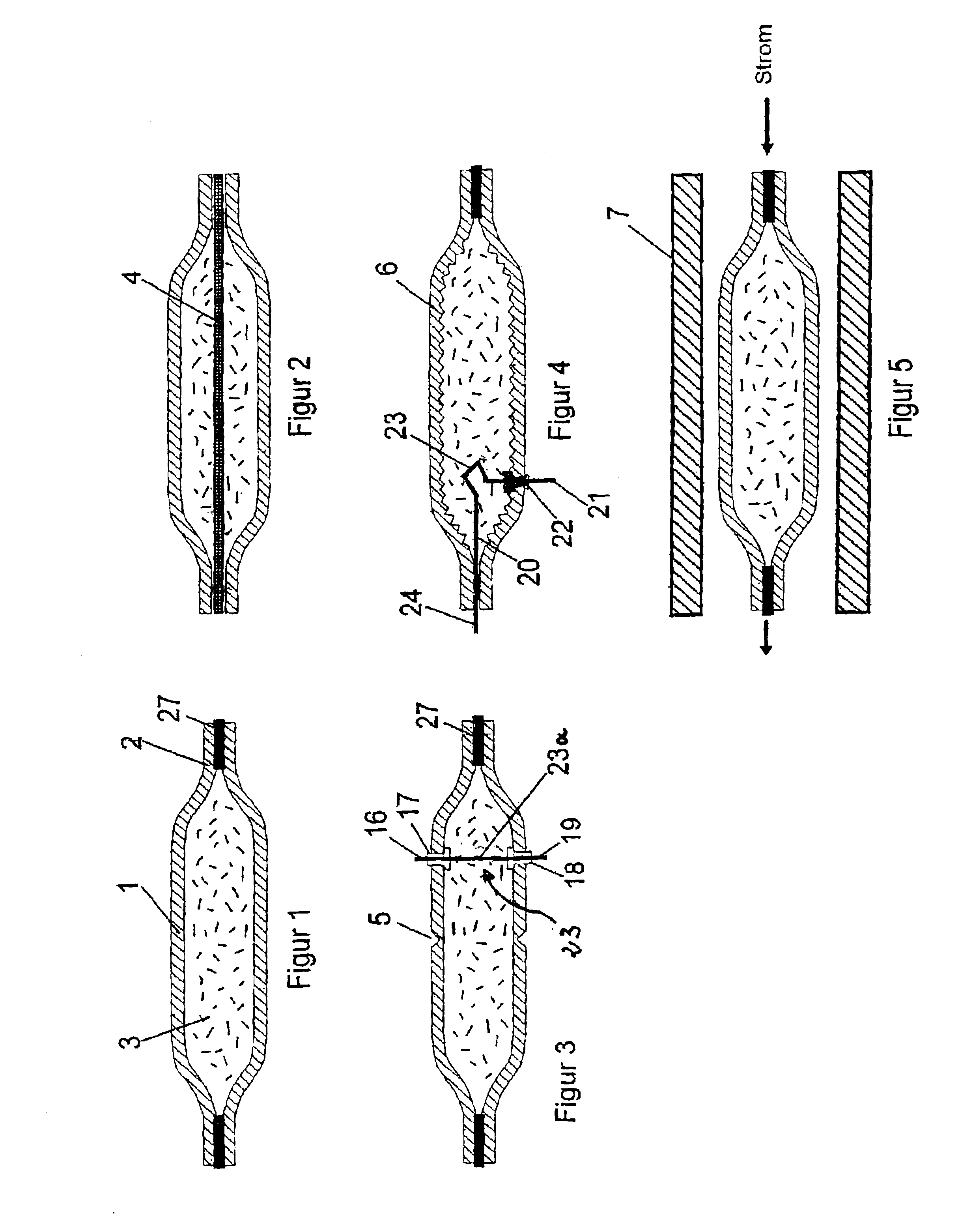
[0041]FIG. 1 schematically shows the basic structure of a first embodiment of a pyrotechnic fuse element. This element consists of a housing 1, preferably in the form of a metal tube which is simply squeezed together at the end portions 2 thereof. In the end portions 2, transverse bores may be provided so that the fuse element can be screwed to a conductor rail or that cable lugs can be screwed onto it. Thus, the end portions 2 form terminal zones for an electric circuit to be protected by the fuse or for the ends of a conductor to be protected by the fuse. The housing 1 is filled either partially or completely with a deflagrating pyrotechnic substance 3—either loosely or pressed—, preferably a propellant charge powder. At least parts of the inner walls of the housing 1 are in thermal contact with the pyrotechnic substance 3.

[0042]If a current with an intensity of the nominal current of the fuse element flows through the housing 1, the latter is heated up as a result of the power di...


PUM


Abstract

The invention relates to a pyrotechnic fuse element having a closed housing consisting of an electrically conductive material, in which an explosive is provided, the housing containing two terminal zones for electric contacting, which are electrically connected by means of the electrically conductive material of the housing, the electric connection of the terminal zones being separable by activating the explosive, and the explosive material being embodied as a deflagrating pyrotechnic substance which is provided in such an amount and is configured such that the electric connection of the terminal zones of the housing is separated in a predetermined time after the deflagrating pyrotechnic substance has been activated.

Description


Claims


Application Information

Patent Timeline
Owner LELL PETER
Why Eureka
Try Eureka