Light source drive, optical information recording apparatus, and optical information recording method

a technology of optical information and recording apparatus, which is applied in the direction of digital signal error detection/correction, instruments, television systems, etc., can solve the problems of inability to achieve high-speed operation, difficult to achieve such a high-voltage process, and considerable price increase, so as to improve the resolution of beam-application energy, improve the time-axis resolution, and fine control of record mark formation

Active Publication Date: 2005-10-11
RICOH KK
View PDF26 Cites 10 Cited by
  • Summary
  • Abstract
  • Description
  • Claims
  • Application Information

AI Technical Summary

Benefits of technology

[0046]Thus, according to the present invention, it becomes also possible to effectively increase the resolution of beam-application energy so as to achieve fine control of record mark formation even in case of high-speed recording, without increasing the time-axis resolution in a beam-application time duration or in a cooling time duration.

Problems solved by technology

Moreover, the following problems may also occur when a high-speed operation is attempted in an optical disk derive.
However, usually, in a micro-fabricated CMOS process, it is difficult to achieve such a high-voltage process.
Accordingly, it may become not possible to achieve high-speed operation, or, even it is possible, a considerable price increase, an increase in consumption power, an increase in size or so may occur for achieving the high-speed operation.

Method used


Image

  • Light source drive, optical information recording apparatus, and optical information recording method
  • Light source drive, optical information recording apparatus, and optical information recording method
  • Light source drive, optical information recording apparatus, and optical information recording method

Examples


first embodiment

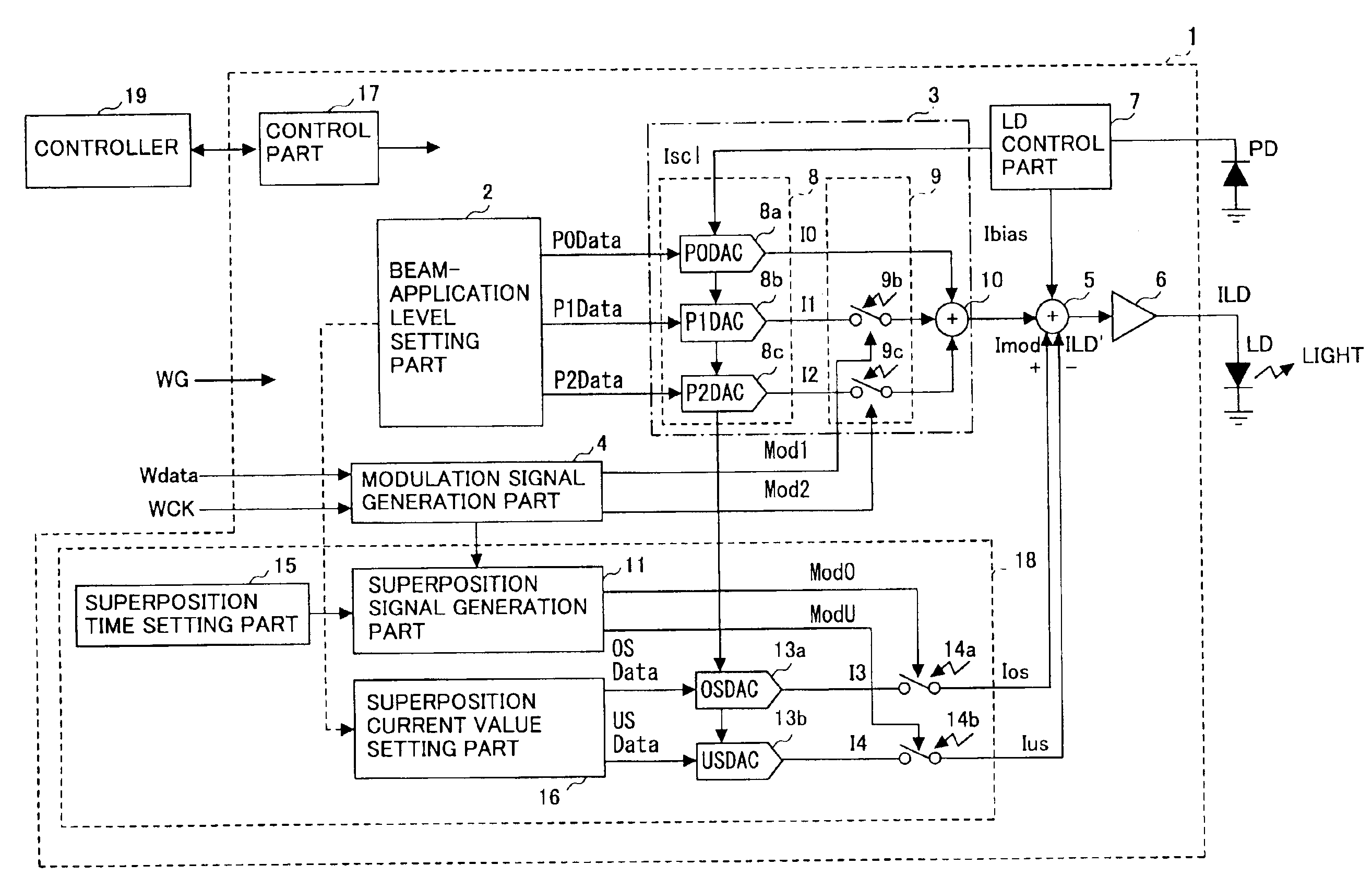
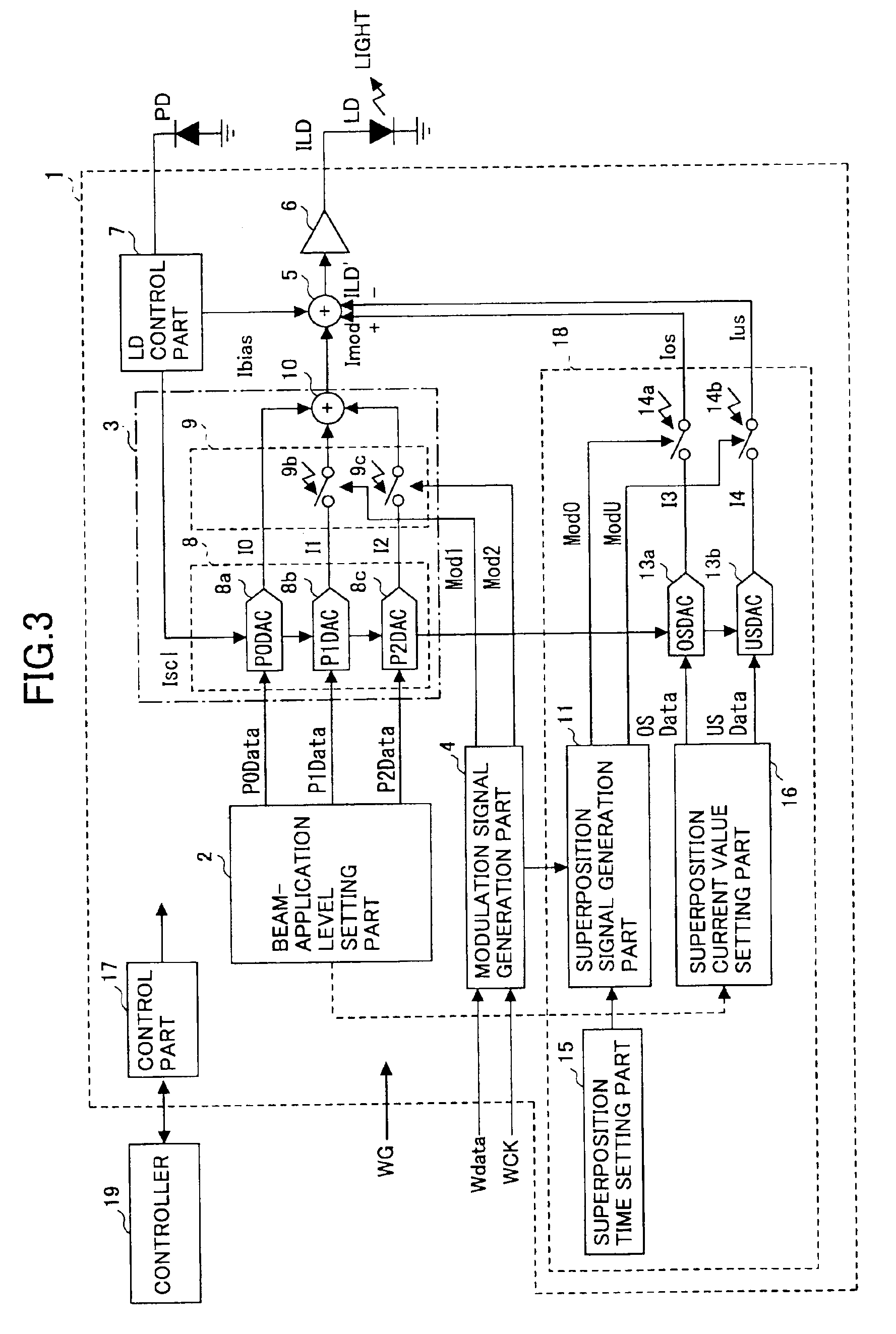
[0049]FIG. 3 shows a block diagram of a configuration of a light source drive according to the present invention;

[0050]FIG. 4 shows waveforms of signals occurring in the light source drive according to the first embodiment of the present invention;

second embodiment

[0051]FIG. 5 shows a block diagram of a configuration of a light source drive according to the present invention;

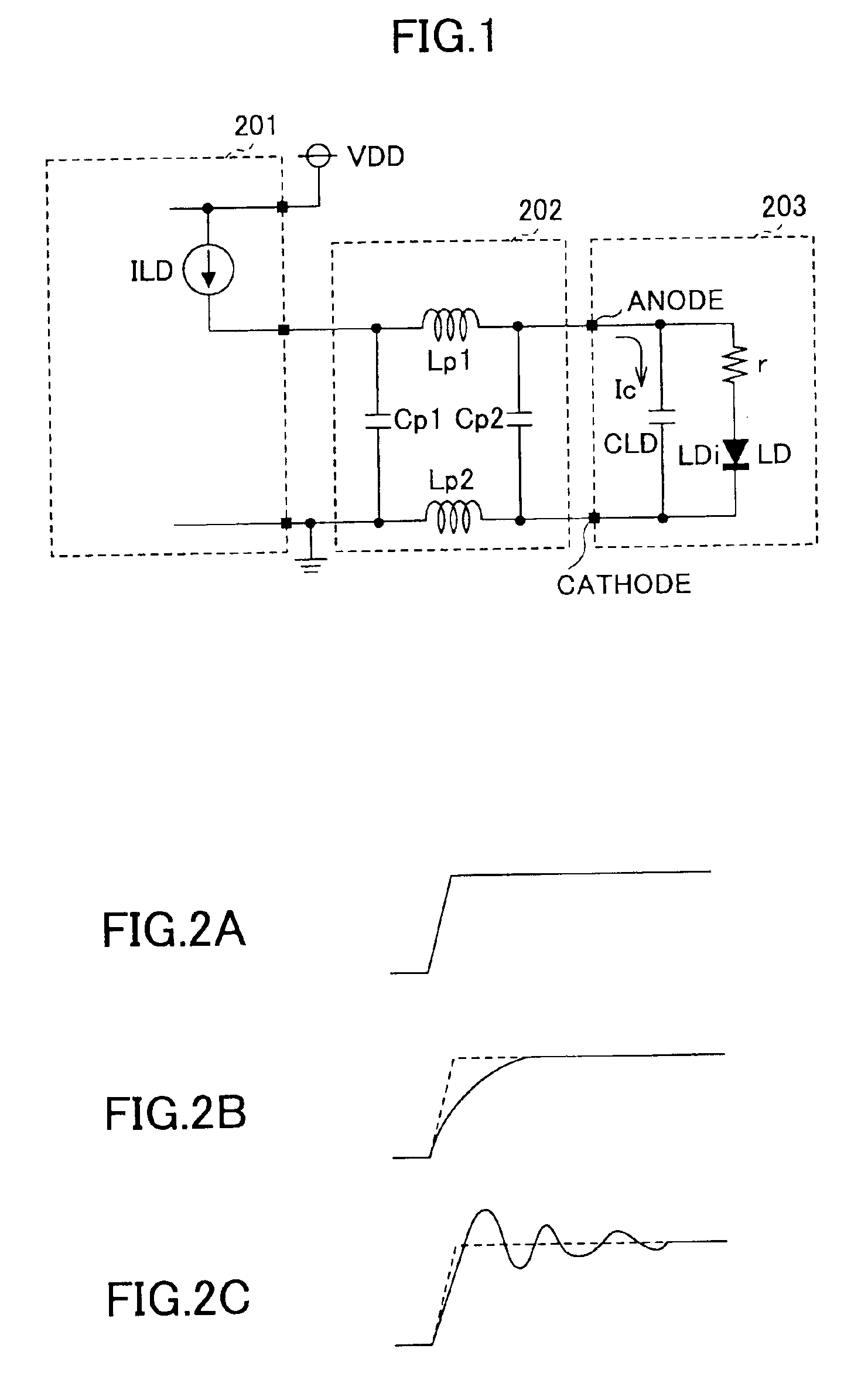
[0052]FIG. 6 shows a circuit diagram for illustrating operation of controlling a ringing of a light waveform otherwise occurring due to a parasitic inductance which is the second problem occurring in a conventional light source drive;

[0053]FIG. 7 shows another example of a configuration of a variable resistance part which may be applied to the second embodiment of the present invention;

[0054]FIGS. 8A, 8B and 8C show another example of the variable resistance part, a waveform of an output signal thereof, and an Id-Vds characteristic of a MOS transistor shown in FIG. 8A, respectively;

third embodiment

[0055]FIG. 9 shows a block diagram of a configuration of a light source drive according to the present invention;


PUM

PropertyMeasurementUnit
voltageaaaaaaaaaa
voltageaaaaaaaaaa
voltageaaaaaaaaaa

Abstract

A light source drive which modulates a light source so as to cause the same to emit a light, includes: a superposition current generation part which generates a superposition current approximately corresponding to a charging/discharging current needed for a capacitance occurring in parallel to the light source for a predetermined time period near at least one of a rising-up part and a decaying-down part of a waveform of a drive current for the light source; and an addition/subtraction part which adds to or subtracts from the drive current the superposition current generated by the superposition current generation part.

Description

BACKGROUND OF THE INVENTION[0001]1. Field of the Invention[0002]The present invention relates to a light source drive which drives a semiconductor laser or so which is a light source used in an optical disk drive or an optical information recording apparatus, such as a CD-R drive, a CD-RW drive, a DVD-R drive, a DVD-RW drive, a DVD+RW drive, a DVD-RAM drive, or so, such an optical information recording apparatus, and an optical information recording method applied therein.[0003]2. Detailed Description of the Related Art[0004]Conventionally, in an optical disk drive, a light source such as a semiconductor laser light source (laser diode or LD) which is a light source is appropriately modulated so as to emit a laser beam, which is applied to an optical information recording medium (optical disk), and thus, information recording and information reproduction are performed thereon. For example, in a phase-change type optical disk used as a CD-RW disk, a DVD+RW disk, etc., an amorphous st...

Claims


Application Information

Patent Timeline
Patent Type & Authority Patents(United States)
IPC IPC(8): G11B7/125G11B7/00G11B7/006H01S5/022H01S5/042
CPCG11B7/0062G11B7/126G11B7/1263G11B11/1053H01S5/0427H01S5/0683
Inventor MASUI, NARUHIROEMA, HIDETOSHI
Owner RICOH KK
Why Eureka
Try Eureka