
Method for designing progressive addition lenses

a technology of progressive addition and lens design, applied in the field of progressive addition lens design, can solve the problems of limiting the designer's ability, unable to achieve the optimum design form, and the lens that will not perform optimally in conjunction with the ey

Inactive Publication Date: 2005-10-18
ESSILOR INT CIE GEN DOPTIQUE
View PDF8 Cites 82 Cited by
  • Summary
  • Abstract
  • Description
  • Claims
  • Application Information

AI Technical Summary

Benefits of technology

[0067]Additionally, if the maximum unwanted astigmatism for one of the surfaces is less than the add power for that surface, the total lens maximum astigmatism can be reduced by the methods of the invention by using the second PAL surface to compensate for the maximum unwanted astigmatism from the other surface. Thus, the total lens maximum astigmatism using the methods of the present invention can be less than about 0.75 times the lens' add power and preferably about 0.5 times the lens' add power.

Problems solved by technology

These methods are disadvantageous in that the lens performance is defined in terms of surface aberrations, namely surface astigmatism and mean power error, surface form, or both surface aberrations and form.
Optimizing lens performance based upon surface calculations results in a lens that will not perform optimally in conjunction with the eye.
Additionally, by limiting the surface shapes to a particular mathematical form, the optimum form of the design cannot be achieved.
Still further, by optimizing the lens performance using surface aberrations, optimization of a PAL having more than one progressive addition surfaces requires optimization of each surface separately limiting the designer's ability to balance the aberration contributions from each of the surfaces to provide the best possible overall lens performance.

Method used


Image

  • Method for designing progressive addition lenses
  • Method for designing progressive addition lenses
  • Method for designing progressive addition lenses

Examples


example 1

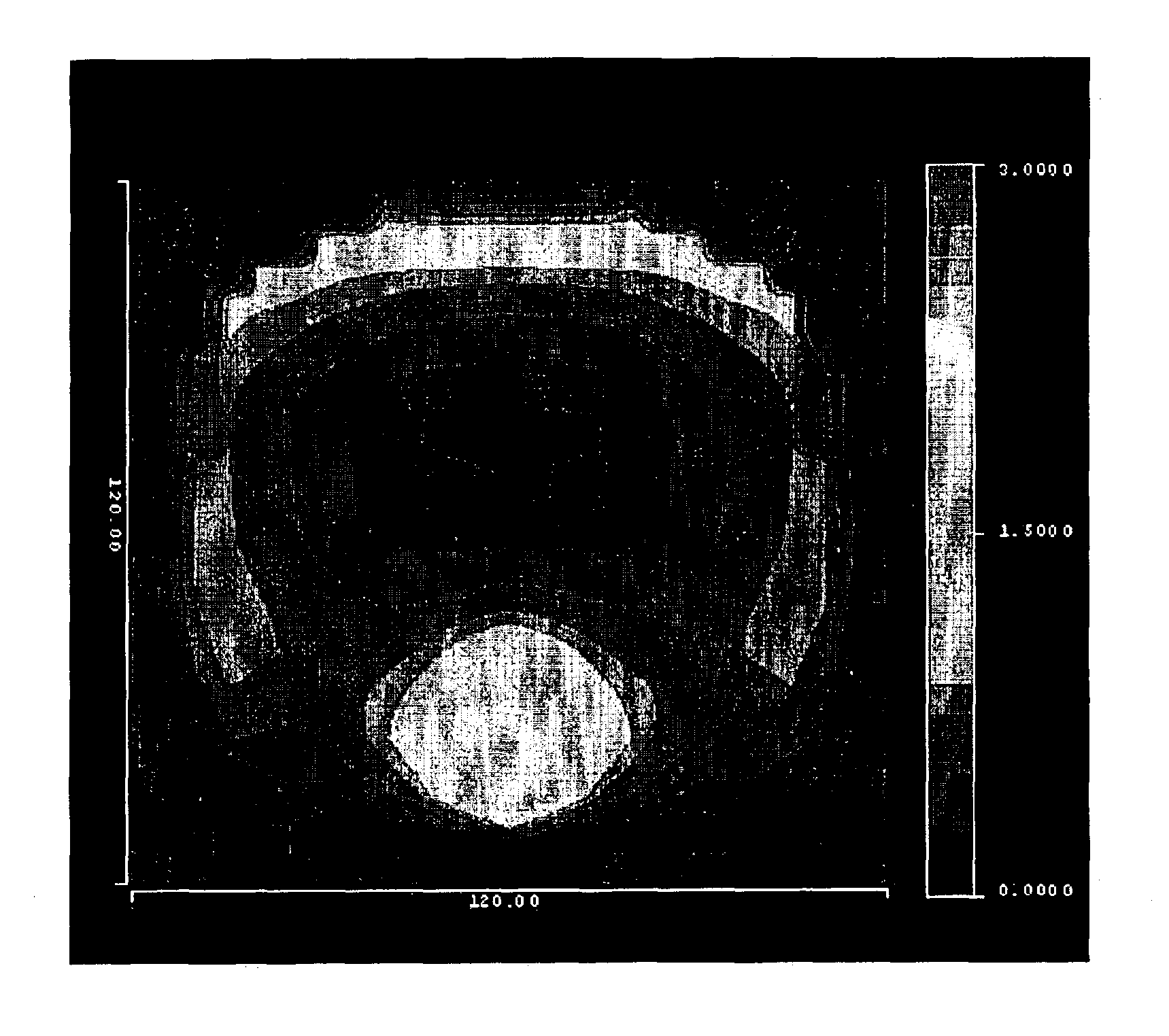
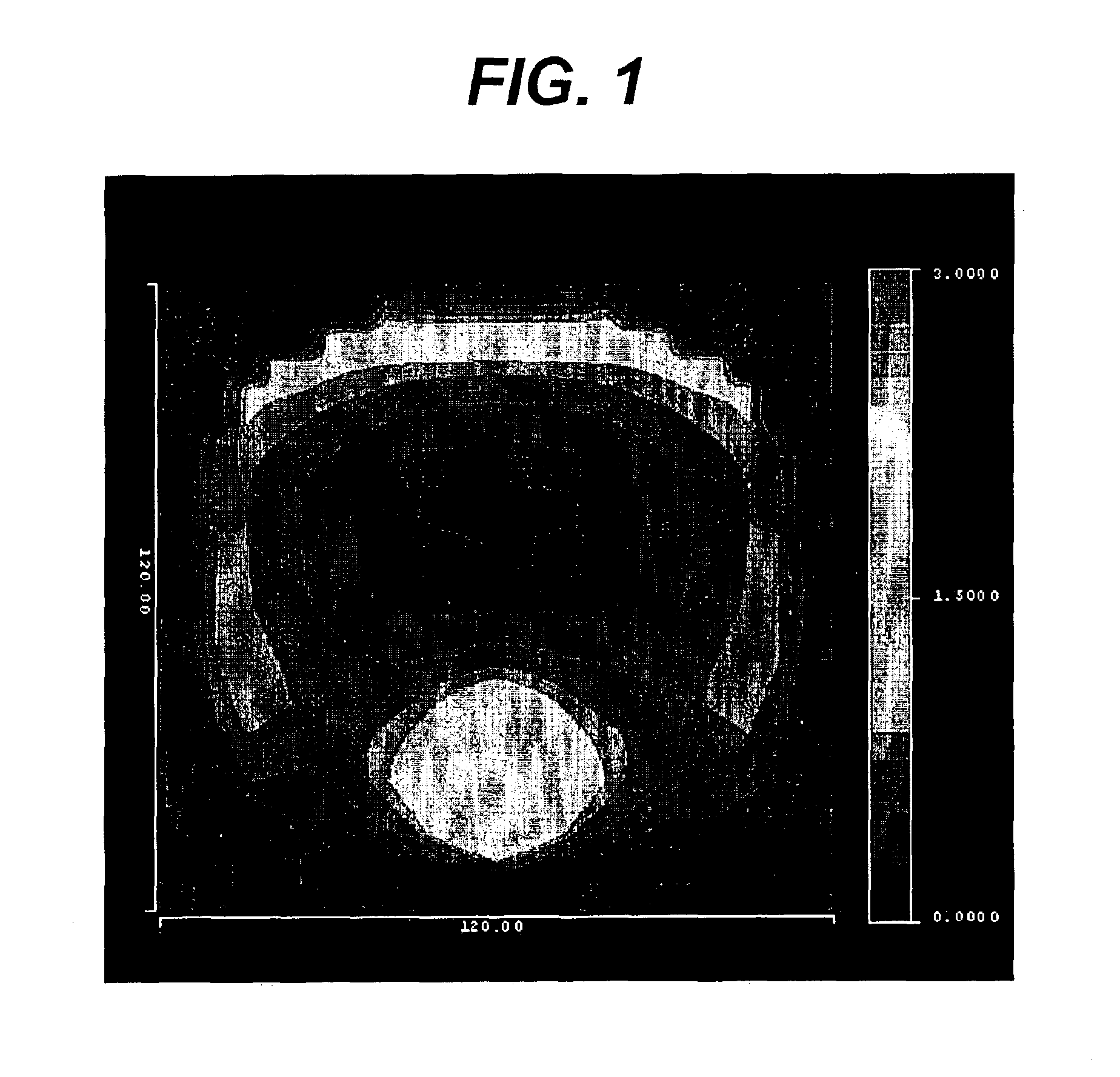
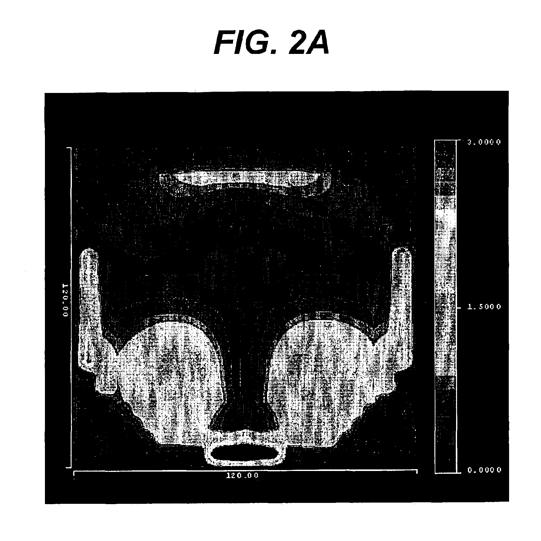
[0069]A baseline example of a lens having two progressive surfaces is provided, which lens has a portion of the total add power on each of the lens surfaces. Additionally, the peaks of the unwanted astigmatism on each of the surfaces were misaligned as described in U.S. Pat. No. 6,149,271. FIGS. 1 through 3 show the add power, the unwanted astigmatism, and the RMS spot size. The plots are from −60 to 60 degrees. The lens diameters in these plots are 60 mm. This, and all subsequent designs have −4.0 diopters of sphere power and 2.0 diopters of add power.

example 2

[0070]A lens having two progressive surfaces was provided using the method of this invention. The lens has a sphere power of −4.0 diopters and 2.0 diopters of add power. The surfaces of the lens were determined by the coefficients of equations of the form of Equation I. The front surface was defined by a base curvature c and a conic constant k and the remainder of the rotationally symmetric aspheric terms are zero. Deltaxy was defined by sets of bi-cubic spline coefficients for a 4 by 8 point grid of evenly spaced points that define the right half of the lens. The lens has a left-right symmetry. The back surface of the lens was defined by a similar function with the conic constant k on the back surface being 0.

[0071]A best fit of the function used to represent the surfaces was made to the surfaces for the baseline design of Example 1. This provided a starting point for the simultaneous optimization of the two surfaces using the method of the invention. The optimization was performed...

example 3

[0075]The lens of Example 3 has two progressive surfaces. The surfaces of this lens, the merit function, and the optimization process are the same as for Example 2 with the following exception. The blur function contribution to the merit function of Equation VIII was used with the relative weighting of the RMS spot size portion of the merit function Wrmsθx,θy adjusted to be the same as the contribution to the merit function based upon the contributions from the unwanted astigmatism Wastθx,θy along the central, vertical corridor.

[0076]A summary of the performance of this lens is shown graphically in FIGS. 7 through 9. In this lens, the maximum unwanted astigmatism for this 2.0 diopters add power lens is approximately 0.75 diopters. Compared to a conventional PAL, this lens shows a large reduction in the maximum unwanted astigmatism and RMS spot size as well as increased near and intermediate reading zone widths.


PUM


Abstract

The invention provides a method for designing progressive surfaces and lenses produced using image blur to construct a merit function. The shape of a lens surface, or surfaces, is arbitrarily defined and optimized to minimize the image blur based merit function.

Description

FIELD OF THE INVENTION[0001]The present invention relates to methods for designing progressive addition lenses. In particular, the invention provides a method for optimizing designs of progressive addition lenses using image blur. The invention also provides a method for simultaneously optimizing multiple progressive surfaces of a lens.BACKGROUND OF THE INVENTION[0002]The use of ophthalmic lenses for the correction of ametropia is well known. For example, multifocal lenses, such as progressive addition lenses (“PALs”), are used for the treatment of presbyopia. The progressive surface of a PAL provides far, intermediate, and near vision in a gradual, continuous progression of increasing dioptric power from far to near focus.[0003]Any number of methods for designing and optimizing progressive surfaces are known. These methods are disadvantageous in that the lens performance is defined in terms of surface aberrations, namely surface astigmatism and mean power error, surface form, or bo...

Claims


Application Information

Patent Timeline
Patent Type & Authority Patents(United States)
IPC IPC(8): G02C7/02
CPCG02C7/061G02C7/028
Inventor WOOLEY, C. BENJAMIN
Owner ESSILOR INT CIE GEN DOPTIQUE
Learn More