Holding device for an optical disk drive

Inactive Publication Date: 2005-10-18
SUNONWEALTH ELECTRIC MACHINE IND
View PDF11 Cites 19 Cited by
  • Summary
  • Abstract
  • Description
  • Claims
  • Application Information

AI Technical Summary

Benefits of technology

[0005]It is an object of the present invention to provide an optical disk d

Problems solved by technology

As a result, holding of the optical disk on the disk tray 91 is not reliable.
Further, the procedure of mounting the pressing members 9

Method used


Image

  • Holding device for an optical disk drive
  • Holding device for an optical disk drive
  • Holding device for an optical disk drive

Examples


Embodiment Construction

[0016]A preferred embodiment in accordance with the present invention will now be described with reference to the accompanying drawings.

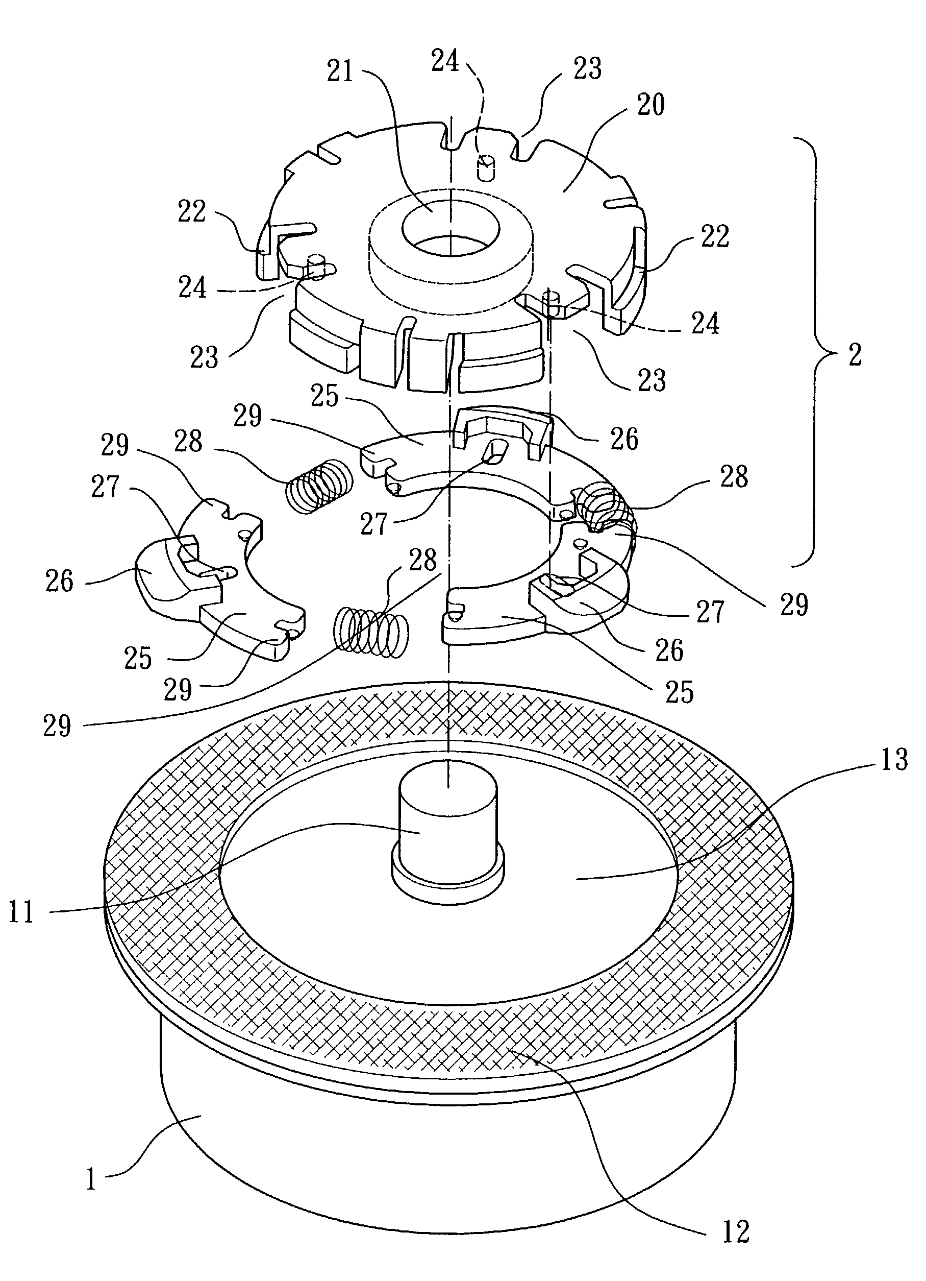
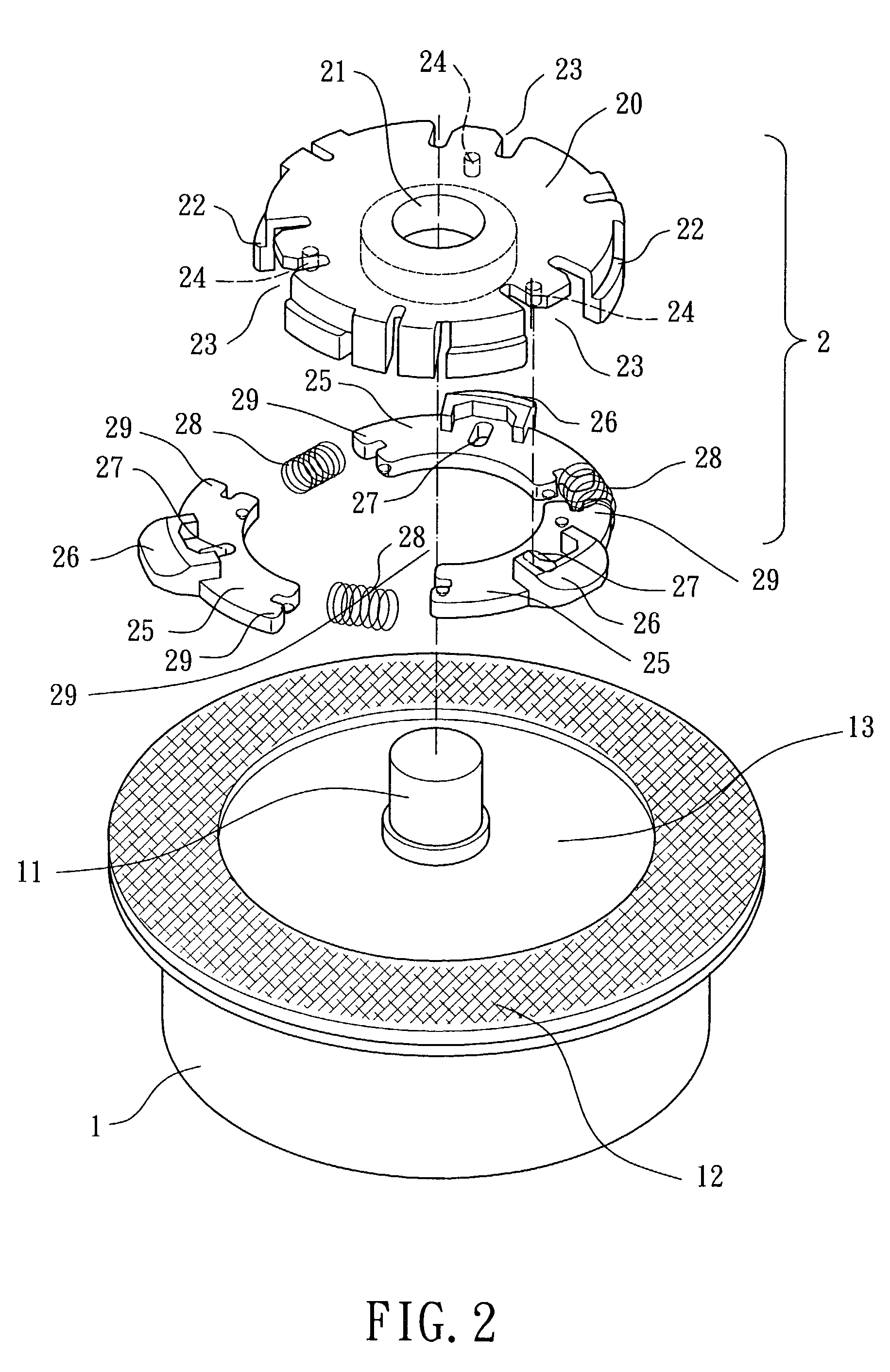
[0017]Referring to FIG. 2, an optical disk drive in accordance with the present invention generally includes a rotor 1 and a holding device 2. The rotor 1 may be of a conventional design. In this embodiment, a shaft 11 is provided on a center of a top side of the rotor 1, and an annular anti-slide plate 12 is mounted on the top side of the rotor 1, providing a disk tray 13 on which an optical disk is mounted.

[0018]The holding device 2 includes a base 20 having a central hole 21 so as to be mounted around the shaft 11 of the rotor 1. The base 20 includes an annular wall 22 extends downwardly along a direction substantially orthogonal to a general plane on which the base 20 lies. A plurality of notched sections 23 are defined in the annular wall 22 and spaced at regular angular intervals. Further, the base 20 includes a plurality of guide pegs 24 each...


PUM


Abstract

A holding device includes a base, a plurality of holding members, and a plurality of elastic elements. The base includes an annular wall extending in a direction substantially orthogonal to a plane on which the base lies. The annular wall includes a plurality of notches. The holding members are mounted in the annular wall and spaced along an angular direction. Each holding member includes a pressing member extending beyond the annular wall of the base via an associated notch of the annular wall. Each elastic element is mounted between two holding members adjacent to each other. A diameter of a circular ring formed by the holding members changes in response to expansion or compression of the elastic elements, causing the pressing member of each said holding member to move between a holding position outside the annular wall and a release position inside the annular wall.

Description

BACKGROUND OF THE INVENTION[0001]1. Field of the Invention[0002]The present invention relates to a holding device for an optical disk drive for holding an optical disk on a disk tray of the optical disk drive in a balanced manner.[0003]2. Description of the Related Art[0004]FIG. 1 of the drawings illustrates an optical disk drive with a conventional holding device for holding an optical disk. The optical disk drive includes a rotor 90 having a disk tray 91 on a top thereof. The holding device 92 includes a plurality of radially extending pressing members 93. Each pressing member 93 is biased by an elastic element 94 to protrude outward in a radial direction for holding an optical disk (not shown) on the disk tray 91. However, the holding forces of the pressing members 93 may vary one from another due to different elastic forces provided by the elastic elements 94. As a result, holding of the optical disk on the disk tray 91 is not reliable. Further, the procedure of mounting the pre...

Claims


Application Information

Patent Timeline
IPC IPC(8): G11B17/028
CPCG11B17/0282
Inventor HORNG, ALEXYIN, TSO-KUO
Owner SUNONWEALTH ELECTRIC MACHINE IND
Why Eureka
Try Eureka