Vehicle lamp with a shield having a double directional illumination structure

a technology of double directional illumination and vehicle lamps, which is applied in vehicle headlamps, transportation and packaging, light and heating equipment, etc., can solve the problems of increasing the complexity and reducing the light efficiency of the combination lamp. , to achieve the effect of maximizing light efficiency

Active Publication Date: 2005-10-25
SL CORP
View PDF8 Cites 1 Cited by
  • Summary
  • Abstract
  • Description
  • Claims
  • Application Information

AI Technical Summary

Benefits of technology

[0014]It is another object of the invention to provide a vehicle lamp of a double directional illumination structure maximizing light efficiency that can emit light into two illuminating directions, using a shield structure for reflecting the light into a second illuminating direction without interfering in the proceeding of the light from a light source into a first illuminating direction.
[0015]And it is still another object of the invention to provide a combination lamp comprising a lamp unit of a double directional illumination structure maximizing light efficiency for a lamp employing the shield structure.
[0016]In order to achieve the aforementioned objects, the inventor conceived that a vehicle lamp of a double directional illumination structure while employing a shield structure, can be implemented in a way that, if a shield for shielding the light from a light source directed in a first illuminating direction is configured to reflect the shielded light into a second illuminating direction. In this manner, it is possible to achieve illumination into two directions without affecting light efficiency into the first illuminating direction. That is, for a vehicle lamp employing the shield structure, the inventor found that it is possible to form a reflecting surface for directing the light into desired illuminating directions, using the already existing shield.

Problems solved by technology

The functions of vehicle lamps are increasingly varied nowaday, which results in that the area occupied by the illumination surfaces, thus the size of the combination lamp is relatively large and the number of parts is also great.
Consequently, the appearance designs of vehicles are significantly limited, and complexity of the combination lamp increases.
If the light from the light source is emitted directly toward the front of a vehicle, the light would hinder eyesight of the other drivers in the other vehicles in the opposite direction of the vehicle.
In addition, the patterns employed in a lamp reflecting mirror cannot also be well represented since the directly emitting light would blinding other than itself.
However, the conventional lamp structure with the altered reflecting surface cannot be easily applied to a lamp with the aforementioned shield structure.
Because the shield would interfere the light proceeded from the bulb or from the reflecting surface to the illumination surfaces, even although the reflecting surface is made larger and altered, only smaller amount of light than desired from the bulb or the reflecting surface can reach on the illumination surfaces.
Since it is impossible to ensure as much light as desired, using the altered reflecting surface as in the conventional technique, it is not easy to configure a vehicle lamp with the double directional illumination structure having a shield.

Method used


Image

  • Vehicle lamp with a shield having a double directional illumination structure
  • Vehicle lamp with a shield having a double directional illumination structure
  • Vehicle lamp with a shield having a double directional illumination structure

Examples


Embodiment Construction

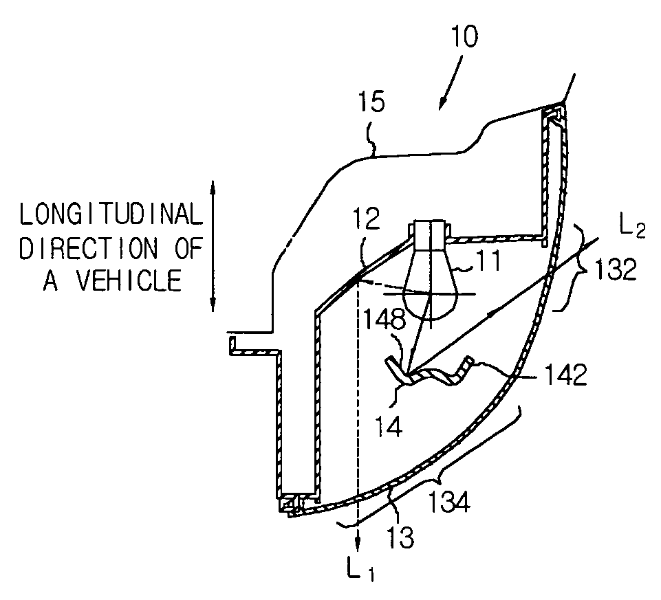
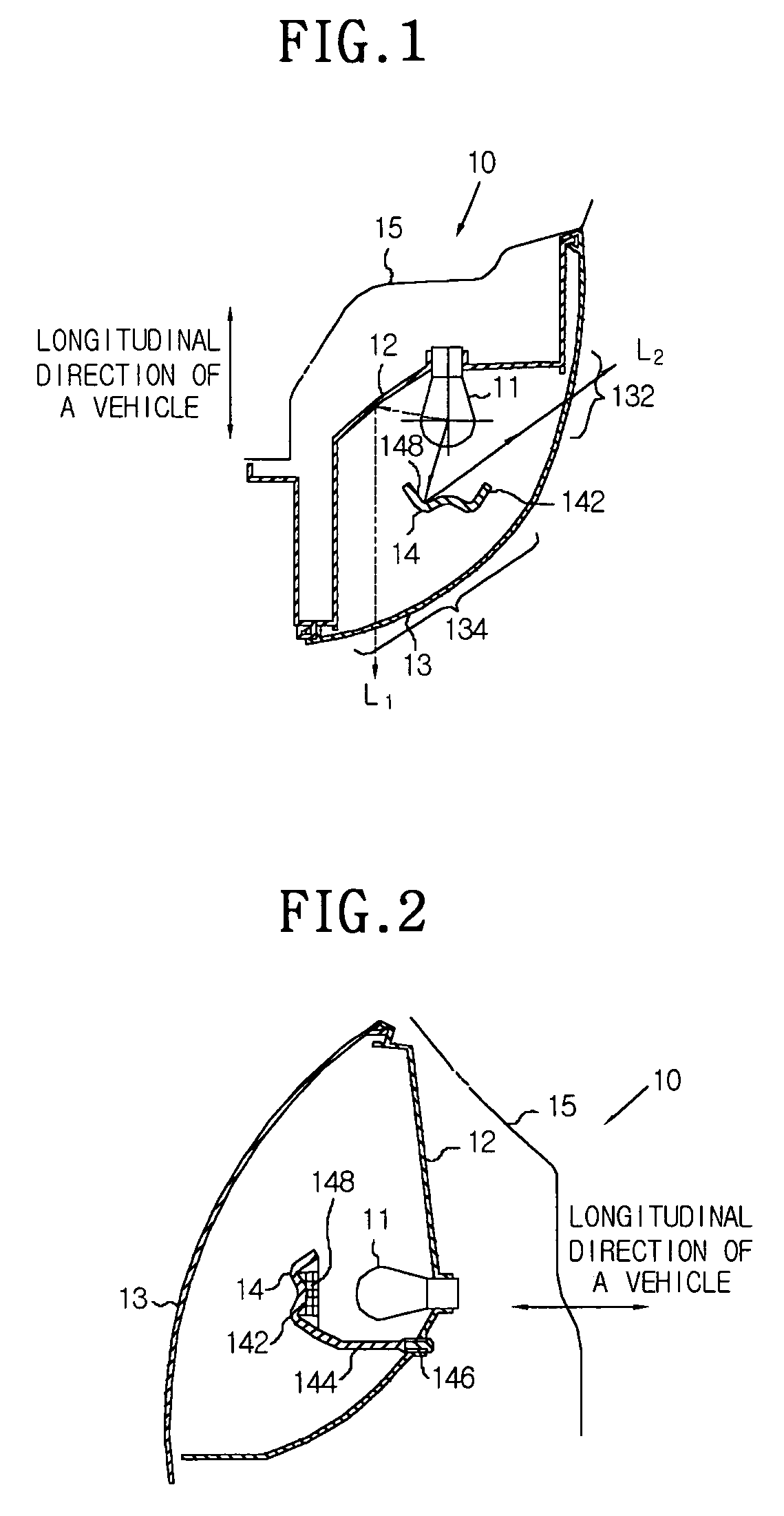
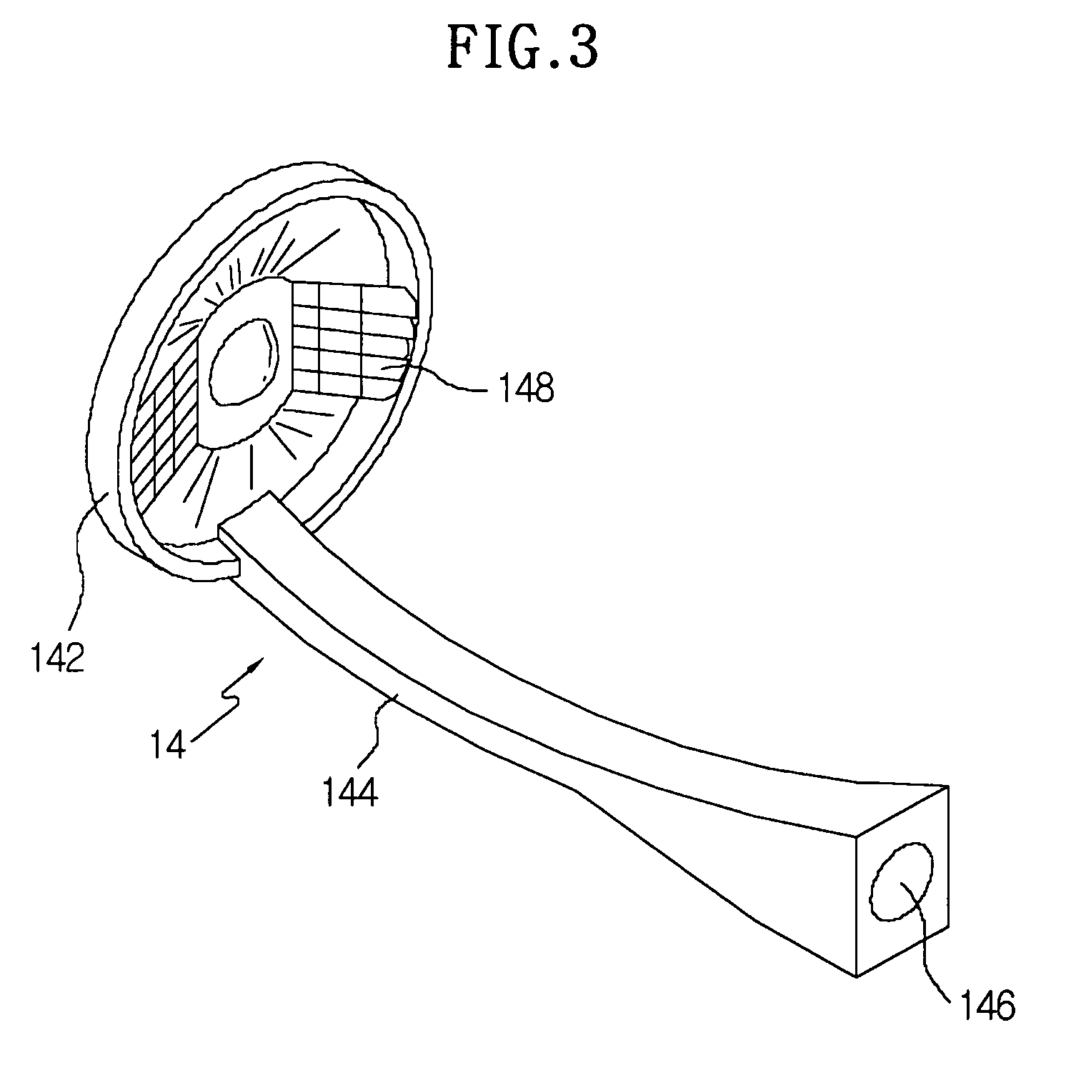
[0028]FIGS. 1 and 2 represent a vehicle lamp 10 having a double directional illumination structure according to a preferred embodiment of the invention. The lamp 10 comprises a light source 11 and a substantially parabola-shaped reflecting surface 12 in the lamp space. The lamp space is defined by a lamp body 15 and an illumination lens 13. The lamp 10 according to the present invention is further provided with a shield 14 for shielding the light directly proceeding from the light source 11 toward the front of the lamp 10. If the reflecting surface 12 of the lamp 10 is formed with a specific pattern, the light reflected by the reflecting surface 12 with the pattern and the light emitted directly from the light source 11, are recognized at the front of the lamp 10, that is from outside of the illumination lens 13, by other drivers or walkers. In this case, the light directly emitted from the light source 11 causes glare, and thus degrades the light pattern reflected in the specific p...


PUM


Abstract

The present invention pertains to a vehicle lamp, comprising: a lamp body in which a first illuminating direction and a second illuminating direction perpendicular to the first illuminating direction are open; an illumination lens for forming a lamp by closing the lamp body and having a first illumination surface through which the light from the light source outgoes to the first illuminating direction, and a second illumination surface through which the light from the light source outgoes to the second illuminating direction; a first reflecting surface for reflecting the light from the light source into the first illuminating direction; a shield for shielding a part of the light proceeded from the light source to the first illuminating direction; and a second reflecting surface formed on the surface facing the light source of the shield, wherein the second reflecting surface reflects and directs the light shielded by the shield into the second illuminating direction. Accordingly, it is possible to provide a vehicle lamp with a shield of a double directional illumination structure that can emit light into a lateral direction without interfering with forward illumination by means of one light source, achieving high light efficiency and maximized spatial utilization.

Description

[0001]This application claims priority to KR Application No. 20-2003-0023775, filed 23 Jul. 2003. The entire contents of this application are incorporated herein by reference.BACKGROUND OF THE INVENTION[0002]1. Technical Field[0003]The present invention relates to a vehicle lamp of a double directional illumination structure having a light source and a two-directional illumination surface, and more particularly, to a vehicle lamp of double directional illumination structure with a shield, wherein the shield shielding a part of the light emitted forward a first illuminating direction from the light source, and reflecting the shielded light into a second illuminating direction.[0004]2. Description of the Prior Art[0005]Generally, a vehicle comprises lighting equipments, such as vehicle lamps, for the purpose of illumination so that a driver can observe objects better in the case of driving at night, and for the purpose of signaling for notifying another vehicle drivers or walkers of t...

Claims


Application Information

Patent Timeline
Patent Type & Authority Patents(United States)
IPC IPC(8): F21V7/00F21V11/16F21V11/00
CPCF21S48/145F21S48/23F21V7/0025F21V11/16F21S41/43F21S43/30
Inventor KIM, DONG-SU
Owner SL CORP
Why Eureka
Try Eureka