
Method for detecting metallic foreign matter and system for detecting metallic foreign matter

a technology for foreign matter and detection methods, applied in the direction of magnetic variables, instruments, and using reradiation, can solve the problems of affecting the reception sensitivity, contaminant such as metal fragments may get mixed in the products, and it is impossible to avoid wear particles or fragments of such stainless steel products from getting mixed in food products,

Inactive Publication Date: 2005-10-25
TOK ENG
View PDF22 Cites 30 Cited by
  • Summary
  • Abstract
  • Description
  • Claims
  • Application Information

AI Technical Summary

Benefits of technology

[0028]The signal analyzing step comprises adding together the detection signal and a phase-inverted signal obtained by phase-inverting an AC excitation power source causing the coil to generate the small magnetic field, thereby eliminating a signal derived from the AC excitation power source from the detection signal, and taking out a signal above a predetermined threshold value, thereby separating a magnetic field signal derived from the inspection object from the detection signal.
[0030]By this eliminating process, the influence of noise generated from peripheral equipment or the like can be removed. It is preferable to provide a magnetizing step having a magnet booster comprising magnet elements in the conveyance path to magnetize the metallic contaminant before the metallic contaminant detecting step. The magnet booster magnetizes the metallic contaminant so that a magnetic field from the metallic contaminant can be detected even more surely.
[0043]Preferably, the signal analyzing means adds together the detection signal and a phase-inverted signal obtained by phase-inverting an AC excitation power source causing the coil to generate the small magnetic field, thereby eliminating a signal derived from the AC excitation power source from the detection signal, and takes out a signal above a predetermined threshold value, thereby separating a magnetic field signal derived from the inspection object from the detection signal.
[0045]Preferably, a magnet booster comprising magnet elements is disposed in the conveyance path upstream of the metallic contaminant detecting means. The magnetizing means magnetizes the metallic contaminant, thus enabling the detection sensitivity to be increased.
[0068]Further, the present invention uses a frequency in the audio-frequency range of from several hundred Hz to several ten kHz as a frequency supplied from the variable-frequency power source to the detection circuit. More specifically, the detection circuit is supplied with a power of a frequency in the neighborhood of 4.5 kHz or 7 kHz. The use of such a low frequency minimizes the eddy current induced in the metallic substance under detection by the alternating magnetic field. Consequently, the effect of the eddy current on the original alternating magnetic field reduces to such an extent that it is almost ignorable.(Consideration of Phase Shift)

Problems solved by technology

In the process of manufacturing these products, for example, contaminants such as metal fragments may get mixed in the products.
It is impossible to avoid wear particles or fragments of such stainless steel products getting mixed in food products.
This may cause the reception sensitivity to be degraded, conversely.
However, it has been difficult to detect metallic contaminants in food products in packaging bags or containers made of electrically conductive materials, such as aluminum pouches or films, by using the conventional sensor coil.
The reason for this is that an eddy current is produced in the containers as the magnetic field becomes strong, thus making it difficult to detect metallic contaminants in the containers.
This detection method suffers unfavorably low detection accuracy (the method can detect only bolts or nuts, for example, which have a diameter not less than about 6 millimeters or 8 millimeters).
In addition, there is a danger that the operator of the X-ray apparatus may be exposed to X-rays.
There are many other problems.
That is, the X-ray apparatus is large in size and costs a great deal to maintain.
Therefore, it is difficult to detect a metallic contaminant with high accuracy.
However, the conventionally proposed metallic contaminant detection using a sensor coil cannot efficiently detect small metal fragments as metallic contaminants of the order of several millimeters in size because of low detection sensitivity.
It is also difficult to detect metallic contaminants in packaging bags or containers made of an electrically conductive material such as aluminum.

Method used


Image

  • Method for detecting metallic foreign matter and system for detecting metallic foreign matter
  • Method for detecting metallic foreign matter and system for detecting metallic foreign matter
  • Method for detecting metallic foreign matter and system for detecting metallic foreign matter

Examples


embodiment 1

[Embodiment 1 of the Invention]

(Structure of Metallic Contaminant Detecting Apparatus)

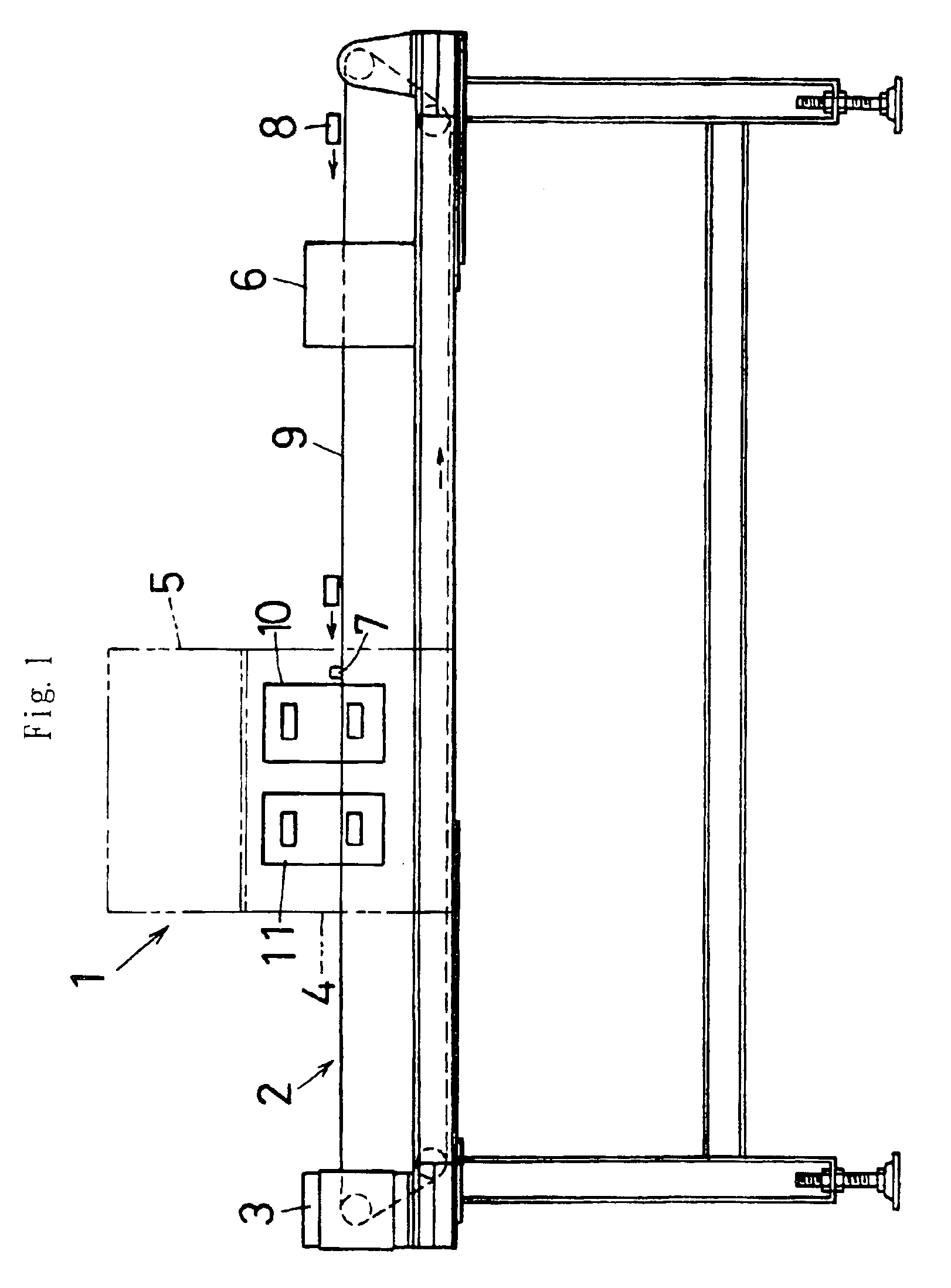
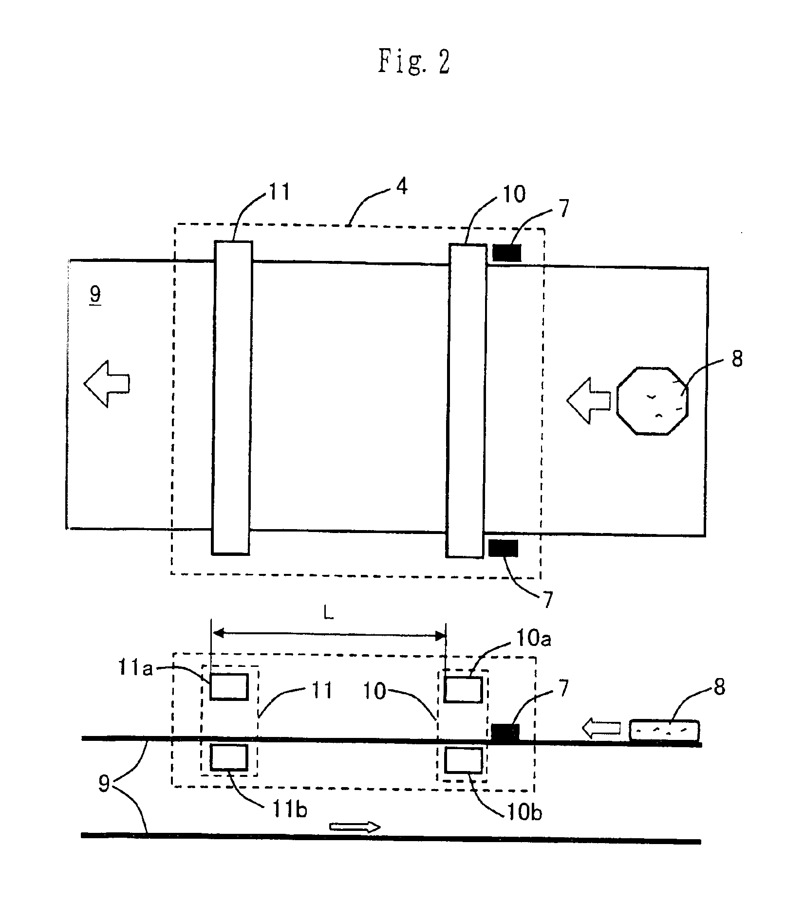
[0089]FIG. 1 shows schematically a metallic contaminant detecting apparatus 1. The metallic contaminant detecting apparatus 1 is adapted to detect a metallic contaminant in an object under inspection, particularly a metallic contaminant mixed in a food product in an aluminum packaging bag, which is a container for wrapping a food product, and to give notice of the detected fact. The metallic contaminant detecting apparatus 1 comprises a belt conveyor 2, a motor 3 for driving, a sensor storage part 4, a control part 5, a magnet booster 6, and so forth. The belt conveyor 2 is a belt conveyor device mounted on a legged frame and adapted to convey an object 8 under inspection at a predetermined speed.

[0090]The belt conveyor 2 has an endless belt 9 that is driven to rotate by a driving motor 3 provided at one end of the belt conveyor 2. An object 8 under inspection is conveyed on the belt 9. In the conv...

embodiment 2

[Embodiment 2] (Crossed Arrangement of Sensor Coils)

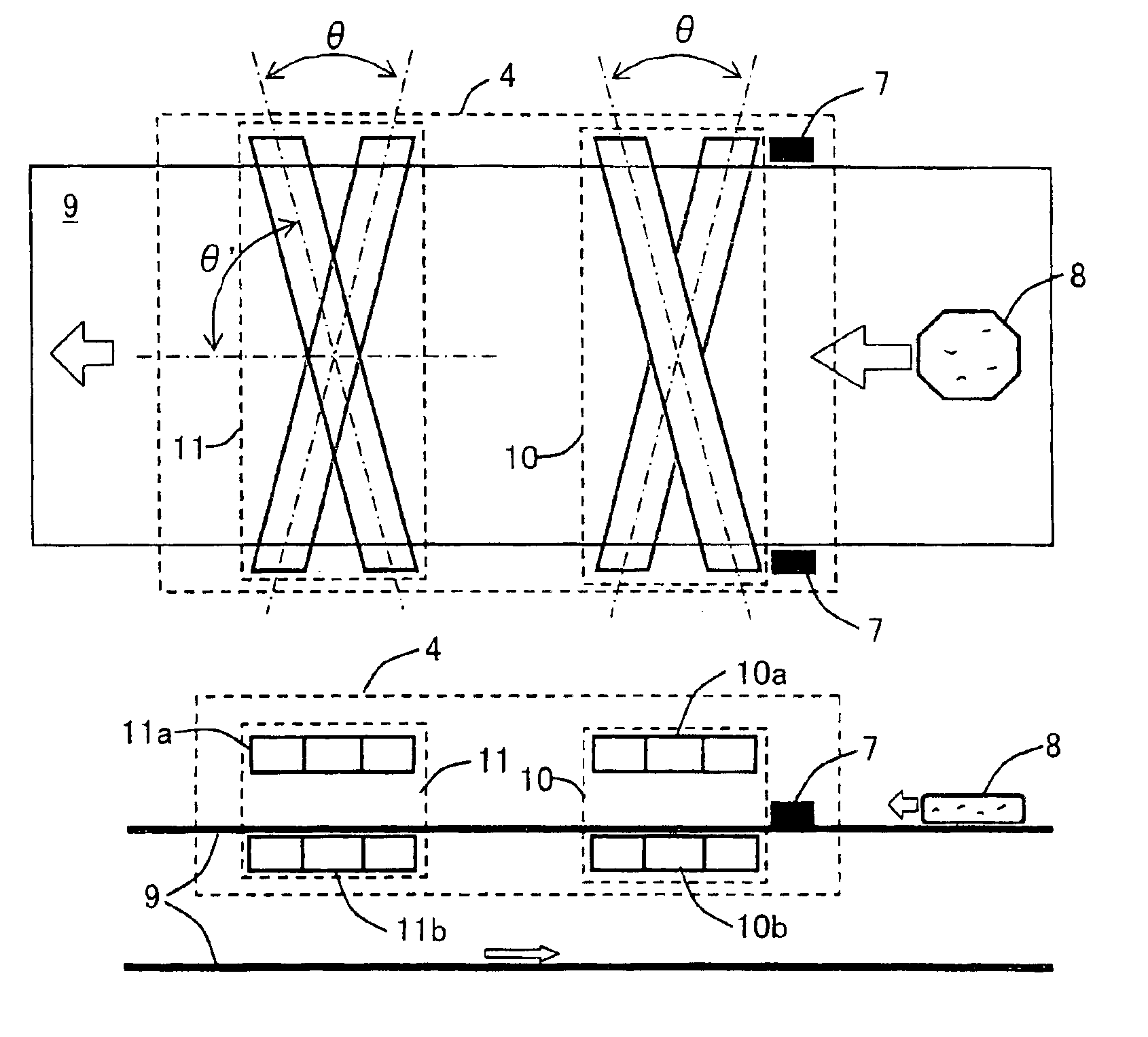
[0118]FIG. 7 is a diagram showing an embodiment in which the sensor coils are disposed to cross each other. The embodiment 2 is basically the same as the above-described embodiment 1. Only a part in which the embodiment 2 differs from the embodiment 1 will be described below. A detailed description of the same portions as those of the embodiment 1 is omitted. In the embodiment 2, the sensor coils are disposed to cross each other.

[0119]More specifically, the sensor coil 10a and the sensor coil 10b, which constitute the first sensor coil, are disposed to cross each other at a predetermined angle θ (as seen from above). The sensor coils 10a and 10b are disposed to extend horizontally in parallel to the belt 9. The sensor coils 10a and 10b intersect the conveying direction of the belt 9 at an angle of (π−θ) / 2 (=θ′) and an angle of (π+θ) / 2 (=θ′+θ), respectively (see FIG. 7). It should be noted that the arrangement of the sensor coils 10...

embodiment 3

[Embodiment 3] (Arrangement of Magnet Booster)

[0122]The embodiment 3 is basically the same as the embodiment 1 or 2. Only a part in which the embodiment 3 differs from the embodiment 1 or 2 will be described below. A detailed description of the same portions as those of the embodiment 1 or 2 is omitted. FIG. 8 is a diagram showing the arrangement of the magnet booster 6. The magnet booster 6 comprises a magnet element 6a and a magnet element 6b. The magnet elements 6a and 6b are installed facing each other vertically across the belt 9. The magnet elements 6a and 6b are disposed such that their like magnetic poles N face toward the belt 9. The magnet booster 6 is arranged so that an inspection object 8 passes between the magnet element 6a and the magnet element 6b.

[0123]It should be noted that each of the magnet elements 6a and 6b may comprise a plurality of magnet elements. Further, the magnet elements 6a and 6b may be arranged or installed in any form, provided that the magnet ele...


PUM

PropertyMeasurementUnit
frequencyaaaaaaaaaa
diameteraaaaaaaaaa
diameteraaaaaaaaaa

Abstract

A metallic contaminant detecting method and apparatus according to the present invention detect metallic contaminants mixed in objects under inspection, such as food products, pharmaceuticals, and materials for industrial use, which are wrapped in electrically conductive packaging materials, e.g. aluminum. A small magnetic field is generated by applying a voltage to coils (10, 11) or supplying an electric current to the coils. A detection magnetic field generated from a metallic contaminant in response to the small magnetic field is detected as a detection voltage or a detection current of the coils (10, 11), and a detection signal is output. The detection signal is analyzed to detect the metallic contaminant. The small magnetic field is created by applying a small voltage or supplying a small electric current to the coils (10, 11) and using a non-linear portion of the magnetic field characteristics of cores constituting the coils (10, 11).

Description

TECHNICAL FIELD[0001]The present invention relates to a metallic contaminant detecting apparatus for detecting a metallic contaminant mixed in an object under inspection. More particularly, the present invention relates to a metallic contaminant detecting method and apparatus for detecting metallic contaminants mixed in objects under inspection, such as food products, pharmaceuticals, and materials for industrial use, which are wrapped in electrically conductive packaging materials, e.g. aluminum. Even more particularly, the present invention relates to a metallic contaminant detecting method and apparatus for detecting metallic contaminants in objects under inspection that are in packaging containers or bags formed by vacuum deposition of aluminum or made of aluminum foil or the like.BACKGROUND ART[0002]Food products, pharmaceuticals, etc. need inspection for contaminants. In the process of manufacturing these products, for example, contaminants such as metal fragments may get mixe...

Claims


Application Information

Patent Timeline
Patent Type & Authority Patents(United States)
IPC IPC(8): G01N27/72G01N27/82G01V3/10G01V3/11
CPCG01N27/82G01V3/104G01N27/72
Inventor KONDO, NOBUKAZU
Owner TOK ENG
Learn More