Metallic contaminant detecting method and apparatus therefor

Inactive Publication Date: 2005-09-22
TOK ENG
View PDF13 Cites 7 Cited by
  • Summary
  • Abstract
  • Description
  • Claims
  • Application Information

AI Technical Summary

Benefits of technology

[0063] Further, in the present invention, the electric current flowing through the sensor coil is set small. That is, as shown in FIG. 6, the present invention uses a region P1, of the B-H characteristics of the core constituting the sensor coil. This region is a non-linear portion where both the magnetic field H and the magnetic flux density B are small. The use of this region allows detection of satisfactory sensitivity even when a metallic contaminant in the inspection object is small in size.
[0064] Let us consider a case where an inspection object passes near the coil at a constant passing speed and at a constant temperature. Typical causes of changing the electric curre

Problems solved by technology

In the process of manufacturing these products, for example, contaminants such as metal fragments may get mixed in the products.
It is impossible to avoid wear particles or fragments of such stainless steel products getting mixed in food products.
This may cause the reception sensitivity to be degraded, conversely.
However, it has been difficult to detect metallic contaminants in food products in packaging bags or containers made of electrically conductive materials, such as aluminum pouches or films, by using the conventional sensor coil.
The reason for this is that an eddy current is produced in the containers as the magnetic field becomes strong, thus making it difficult to detect metallic contaminants in the containers.
This detection method suffers unfavorably low detection accuracy (the

Method used


Image

  • Metallic contaminant detecting method and apparatus therefor
  • Metallic contaminant detecting method and apparatus therefor
  • Metallic contaminant detecting method and apparatus therefor

Examples


Example

[Embodiment 1 of the Invention]

(Structure of Metallic Contaminant Detecting Apparatus)

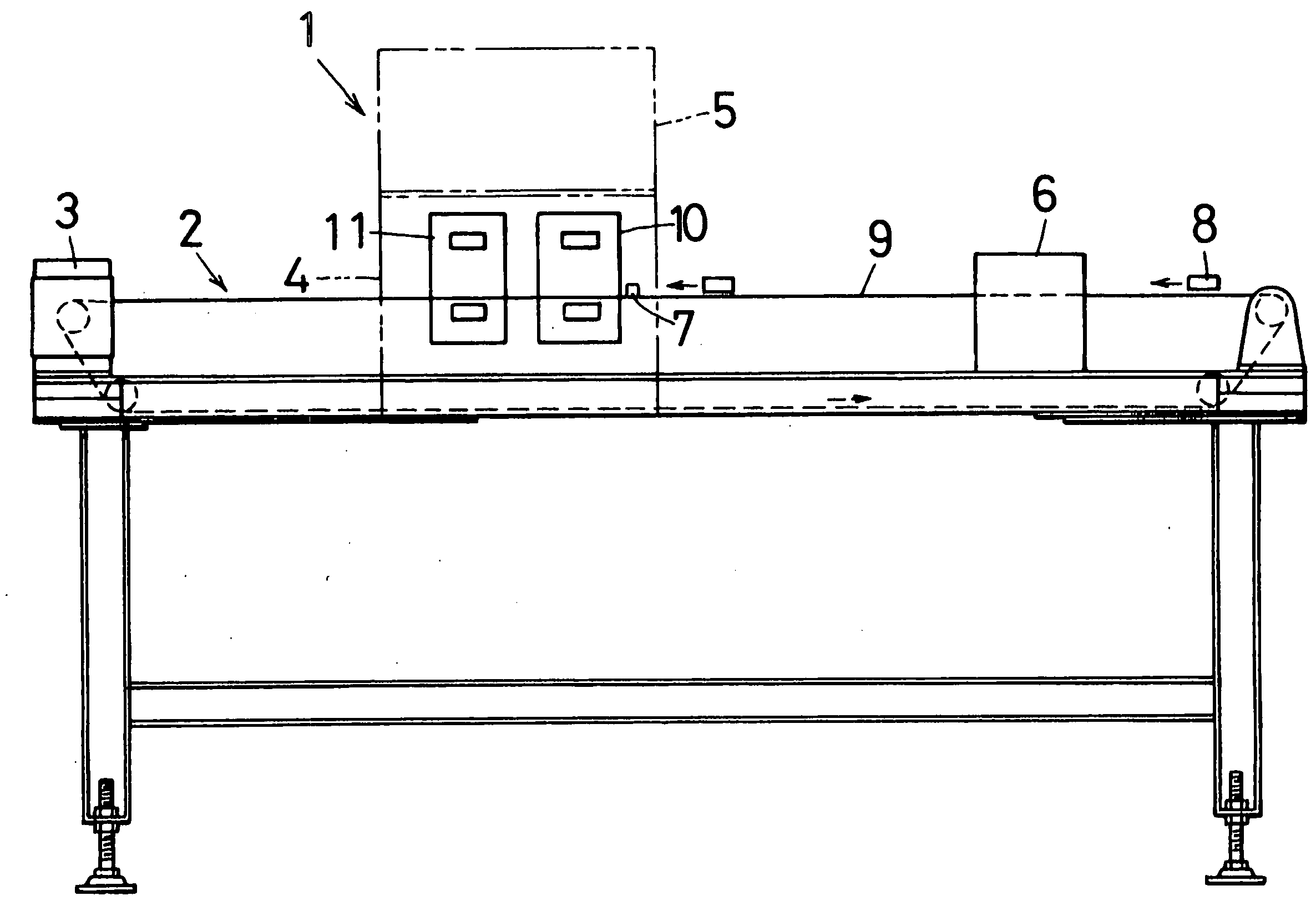
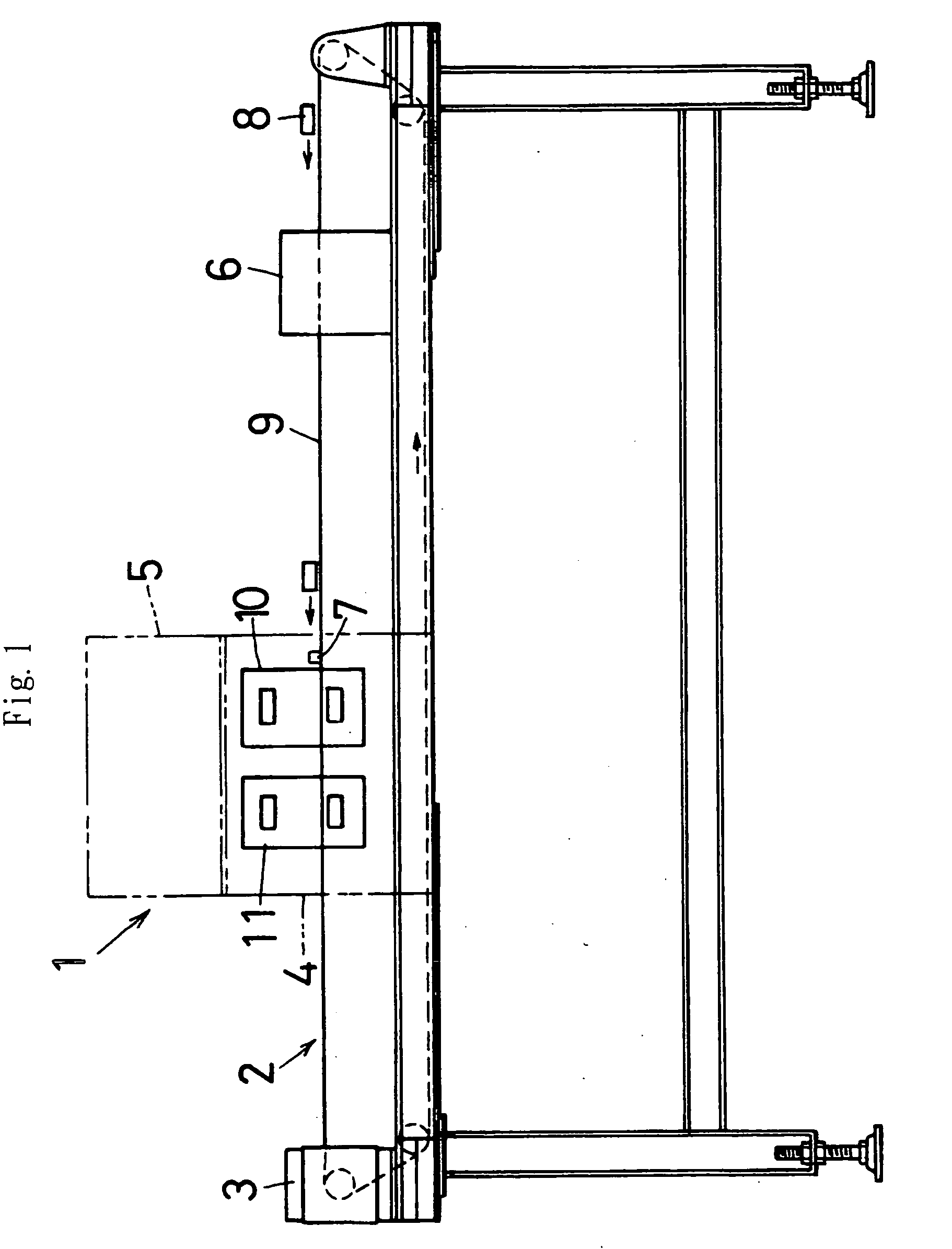
[0088]FIG. 1 shows schematically a metallic contaminant detecting apparatus 1. The metallic contaminant detecting apparatus 1 is adapted to detect a metallic contaminant in an object under inspection, particularly a metallic contaminant mixed in a food product in an aluminum packaging bag, which is a container for wrapping a food product, and to give notice of the detected fact. The metallic contaminant detecting apparatus 1 comprises a belt conveyor 2, a motor 3 for driving, a sensor storage part 4, a control part 5, a magnet booster 6, and so forth. The belt conveyor 2 is a belt conveyor device mounted on a legged frame and adapted to convey an object 8 under inspection at a predetermined speed.

[0089] The belt conveyor 2 has an endless belt 9 that is driven to rotate by a driving motor 3 provided at one end of the belt conveyor 2. An object 8 under inspection is conveyed on the belt 9. In the...

Example

[Embodiment 2] (Crossed Arrangement of Sensor Coils)

[0117]FIG. 7 is a diagram showing an embodiment in which the sensor coils are disposed to cross each other. The embodiment 2 is basically the same as the above-described embodiment 1. Only a part in which the embodiment 2 differs from the embodiment 1 will be described below. A detailed description of the same portions as those of the embodiment 1 is omitted. In the embodiment 2, the sensor coils are disposed to cross each other.

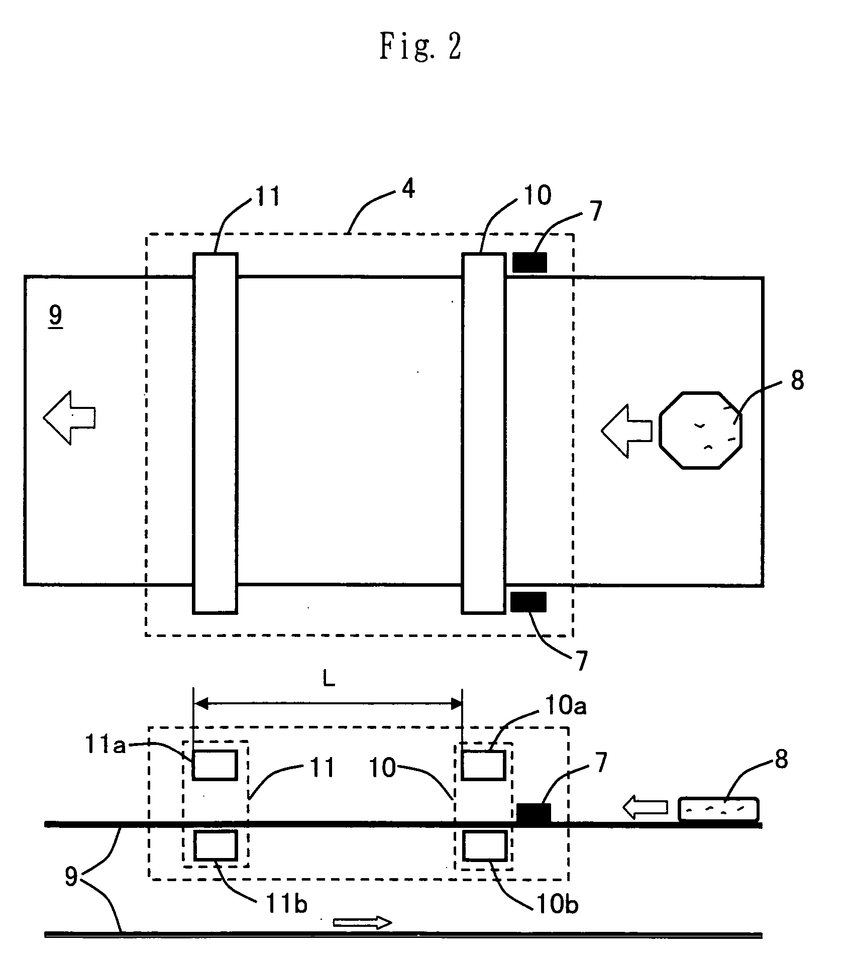
[0118] More specifically, the sensor coil 10a and the sensor coil 10b, which constitute the first sensor coil, are disposed to cross each other at a predetermined angle θ (as seen from above) . The sensor coils 10a and 10b are disposed to extend horizontally in parallel to the belt 9. The sensor coils 10a and 10b intersect the conveying direction of the belt 9 at an angle of (π−θ) / 2 (=θ′) and an angle of (π+θ) / 2 (=θ′+θ), respectively (see FIG. 7). It should be noted that the arrangement of the sensor coi...

Example

[Embodiment 3] (Arrangement of Magnet Booster)

[0121] The embodiment 3 is basically the same as the embodiment 1 or 2. Only a part in which the embodiment 3 differs from the embodiment 1 or 2 will be described below. A detailed description of the same portions as those of the embodiment 1 or 2 is omitted. FIG. 8 is a diagram showing the arrangement of the magnet booster 6. The magnet booster 6 comprises a magnet element 6a and a magnet element 6b. The magnet elements 6a and 6b are installed facing each other vertically across the belt 9. The magnet elements 6a and 6b are disposed such that their like magnetic poles N face toward the belt 9. The magnet booster 6 is arranged so that an inspection object 8 passes between the magnet element 6a and the magnet element 6b.

[0122] It should be noted that each of the magnet elements 6a and 6b may comprise a plurality of magnet elements. Further, the magnet elements 6a and 6b may be arranged or installed in any form, provided that the magnet...


PUM


Abstract

A metallic contaminant detecting method and apparatus according to the present invention detect metallic contaminants mixed in objects under inspection, such as food products, pharmaceuticals, and materials for industrial use, which are wrapped in electrically conductive packaging materials, e.g. aluminum. A small magnetic field is generated by applying a voltage to coils (10, 11) or supplying an electric current to the coils. A detection magnetic field generated from a metallic contaminant in response to the small magnetic field is detected as a detection voltage or a detection current of the coils (10, 11), and a detection signal is output. The detection signal is analyzed to detect the metallic contaminant. The small magnetic field is created by applying a small voltage or supplying a small electric current to the coils (10, 11) and using a non-linear portion of the magnetic field characteristics of cores constituting the coils (10, 11).

Description

TECHNICAL FIELD [0001] The present invention relates to a metallic contaminant detecting apparatus for detecting a metallic contaminant mixed in an object under inspection. More particularly, the present invention relates to a metallic contaminant detecting method and apparatus for detecting metallic contaminants mixed in objects under inspection, such as food products, pharmaceuticals, and materials for industrial use, which are wrapped in electrically conductive packaging materials, e.g. aluminum. Even more particularly, the present invention relates to a metallic contaminant detecting method and apparatus for detecting metallic contaminants in objects under inspection that are in packaging containers or bags formed by vacuum deposition of aluminum or made of aluminum foil or the like. BACKGROUND ART [0002] Food products, pharmaceuticals, etc. need inspection for contaminants. In the process of manufacturing these products, for example, contaminants such as metal fragments may get...

Claims


Application Information

Patent Timeline
IPC IPC(8): G01N27/72G01N27/82G01V3/10G01V3/11
CPCG01V3/104G01N27/82G01N27/72
Inventor KONDO, NOBUKAZU
Owner TOK ENG
Why Eureka
Try Eureka