Multi-point staging strategy for low emission and stable combustion

a multi-point, stable combustion technology, applied in the ignition of turbine/propulsion engines, combustion control, combustion types, etc., can solve the problems of high dynamic pressure, unstable combustion, and excessive co and uhc in the quenching

a multi-point, stable combustion technology, applied in the ignition of turbine/propulsion engines, combustion control, combustion types, etc., can solve the problems of high dynamic pressure, unstable combustion, and excessive co and uhc in the quenching

US6962055B2Inactive Publication Date: 2005-11-08UNITED TECH CORP

Image

  • Multi-point staging strategy for low emission and stable combustion
  • Multi-point staging strategy for low emission and stable combustion
  • Multi-point staging strategy for low emission and stable combustion

Examples


Embodiment Construction

)

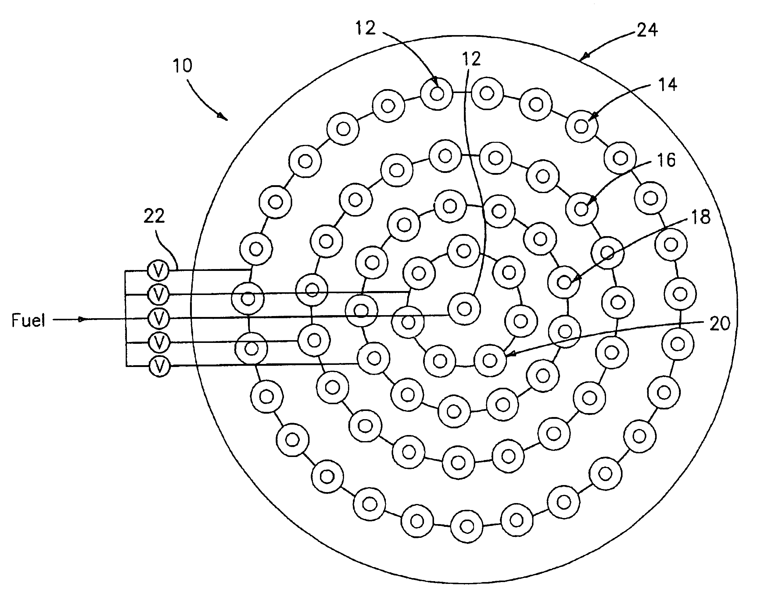
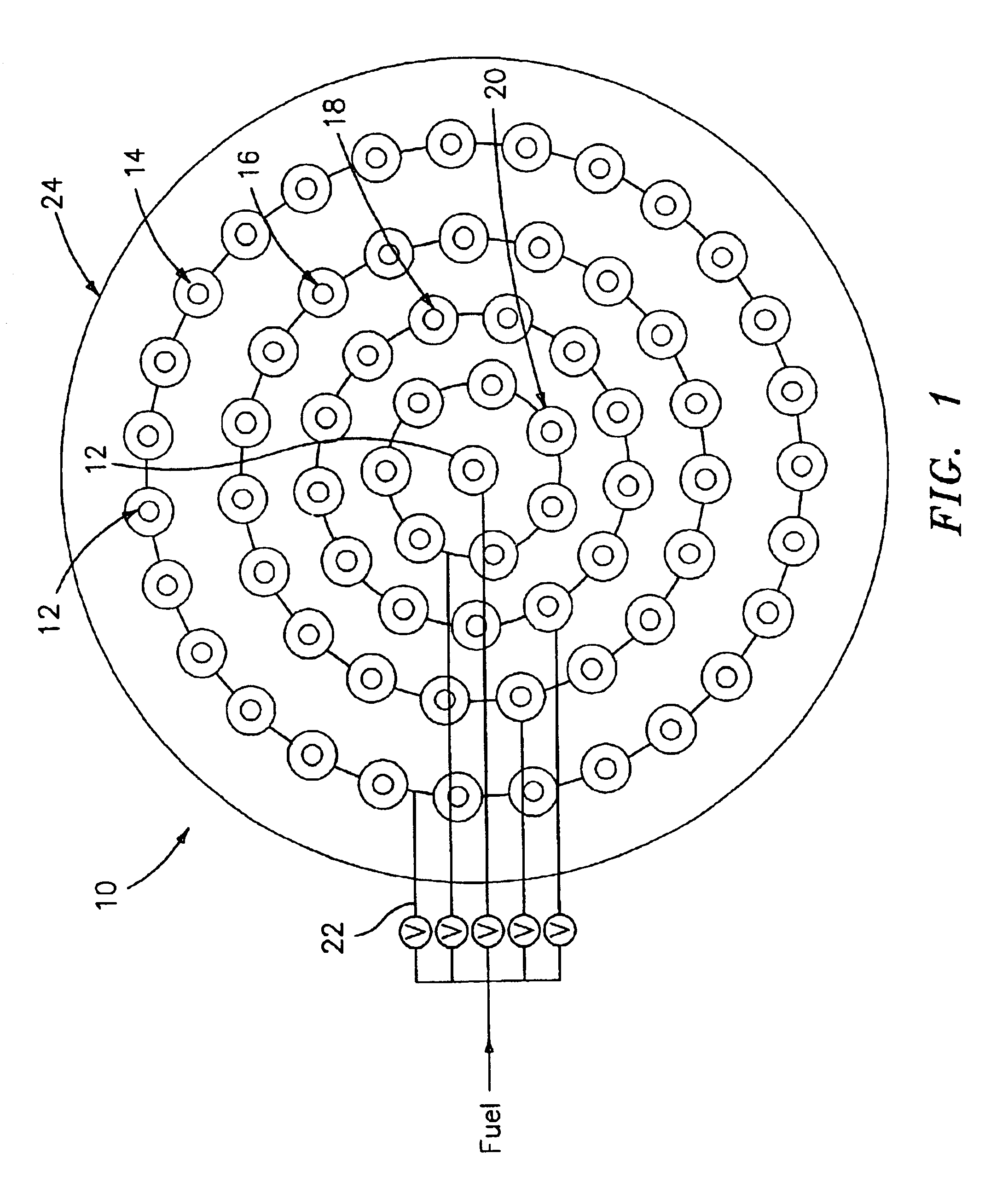
[0016]Referring now to the drawings, FIG. 1 illustrates a first embodiment of a multi-point injector 10 in accordance with the present invention. The multi-point injector 10 has nozzles 12 for injecting a fuel-air mixture into a combustor stage of a gas turbine engine. The nozzles 12 are arranged in a plurality of arrays. In the embodiment of FIG. 1, the nozzles 12 are arranged in four concentric rings 14, 16, 18, and 20 with an optional nozzle in the center. While the nozzle arrays have been shown to be concentric rings, it should be recognized that the nozzles 12 can be arranged in different configurations, including but not limited to squares, rectangles, hexagons, or parallel lines.

[0017]In accordance with the present invention, means for independently controlling the fuel flow rate for each of the rings 14, 16, 18, and 20 and the optional center nozzle are provided. The fuel flow rate controlling means comprises a different fuel circuit 22 for each ring 14, 16, 18, and 20 and ...


PUM


Abstract

The present invention relates to an improved multi-point injector for use in a gas turbine engine or other types of combustors. The multi-point fuel injector has a plurality of nozzles arranged in at least two arrays such as concentric rings. The injector further has different fuel circuits for independently controlling the fuel flow rate for the nozzles in each of the arrays. Each of the nozzles include a fluid channel and one or more swirler vanes in the fluid channel for creating a swirling flow within the fluid channel. A method for injecting a fuel / air mixture into a combustor stage of a gas turbine engine is also described. At least one zone has a flame hot enough to stabilize the entire combustor flame.

Description

BACKGROUND OF THE INVENTION[0001]The present invention relates to a multi-point fuel injector for use in a combustor of a gas turbine engine or other types of combustors.[0002]One of the biggest challenges for gas turbines, especially for industrial applications, is to have good emission performance and combustion stability for a wide range of power settings and ambient condition. If one has an industrial gas turbine with low emissions of NOx, CO and UHC at 100% power, as one reduces the power, which is usually done by reducing the amount of fuel to the engine, the fuel / air mixture in the combustor typically gets leaner. The leaner mixture of fuel / air lowers the flame temperature and creates a flame which can be quenched relatively easily by a cooler combustor wall or cooling film on the combustor wall. The quenching effect creates excessive CO and UHC and high dynamic pressure. If they are not further oxidized, the CO and UHC become pollutants. The other issue associated with too l...

Claims


Application Information

Patent Timeline
08 Nov 2005
Publication
US6962055B2
IPC
F23R3/28; F23R3/34; F23N1/00
CPC
F23N1/002; F23R3/286; F23R3/343; F23R3/346; F23C2201/20; F23D2900/14021; F23N2025/08; F23N2037/02
Inventors
CHEN, ALEXANDER G.; KENDRICK, DONALD W.