Textile machine and control method thereof

a technology of textile machine and control method, which is applied in the field of textile machine, can solve the problems of not being able to alter the tensioning of weft and warp yarn, not being able to modify the pulling tension applied, and not being able to alter the compactness or density of fabri

Inactive Publication Date: 2005-11-08
ZORINI LUIGI OMODEO
View PDF10 Cites 5 Cited by
  • Summary
  • Abstract
  • Description
  • Claims
  • Application Information

AI Technical Summary

Benefits of technology

[0015]It is an aim of the present invention to solve the above mentioned drawbacks. In particular, the present invention aims at making available a textile machine and the control method thereof, that are able to vary tensioning of the weft yarns when supplied to the sickles, without stopping operation of the machine.
[0016]Another aim of the invention is to provided a textile machine, and the control method thereof, allowing the take-down tensioning of the textile product coming out of the machine to be varied without stopping operation of the machine.
[0017]It is a further aim of the invention to provide a textile machine and the control method thereof, allowing articles of manufacture having portions of different compactness, in a direction both parallel and transverse to the extension of the product itself, to be made in an automatic manner.

Problems solved by technology

Consequently, it is not possible to alter tensioning of the weft and warp yarns when supplied to the respective bars without stopping operation of the machine, neither is it possible to modify the pulling tension applied when the finished product is removed from the machine.
Therefore, by adopting these modalities of use of the loom it is not possible to alter the fabric compactness or density both in a transverse direction and in a direction parallel to the extension of the textile product, without stopping operation of the machine.
In addition, exactly due to the fact that the warp and weft yarns are fed to the healds and sickles respectively at a constant tension and the textile product is caused to slide between the take-down rollers at a constant tension in time, it is not possible to obtain particular aesthetic effects through a controlled variation of the fabric compactness, without stopping operation of the machine, said aesthetic effects comprising alternations of thinner and more compact regions, narrowing or shrinkage of the textile product along a direction substantially perpendicular to the movement direction in which the textile product itself is moved by the take-down rollers, etc.

Method used


Image

  • Textile machine and control method thereof
  • Textile machine and control method thereof
  • Textile machine and control method thereof

Examples


Embodiment Construction

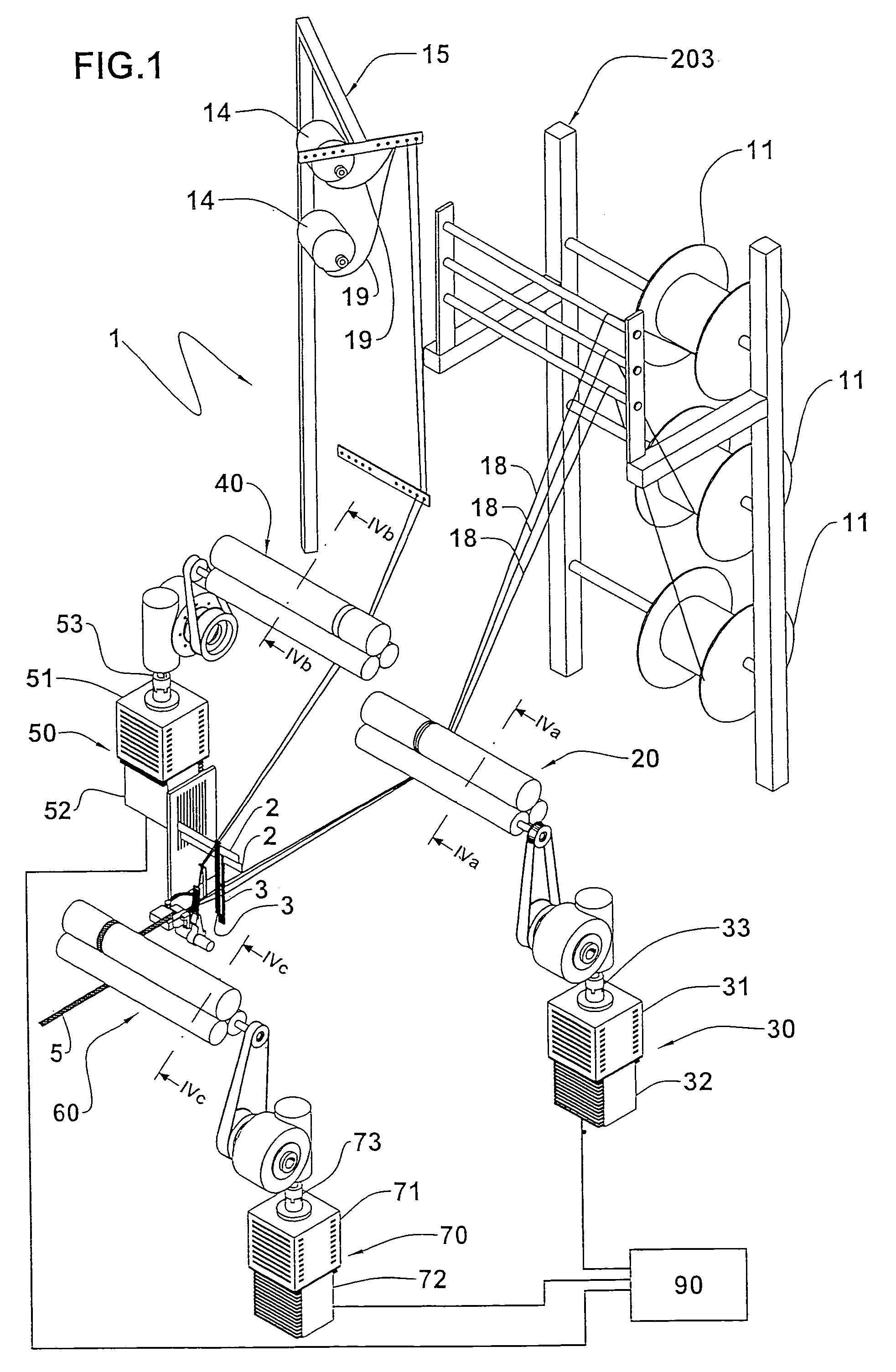
[0028]With reference to the drawings, a textile machine in accordance with the present invention has been generally identified by reference numeral 1.

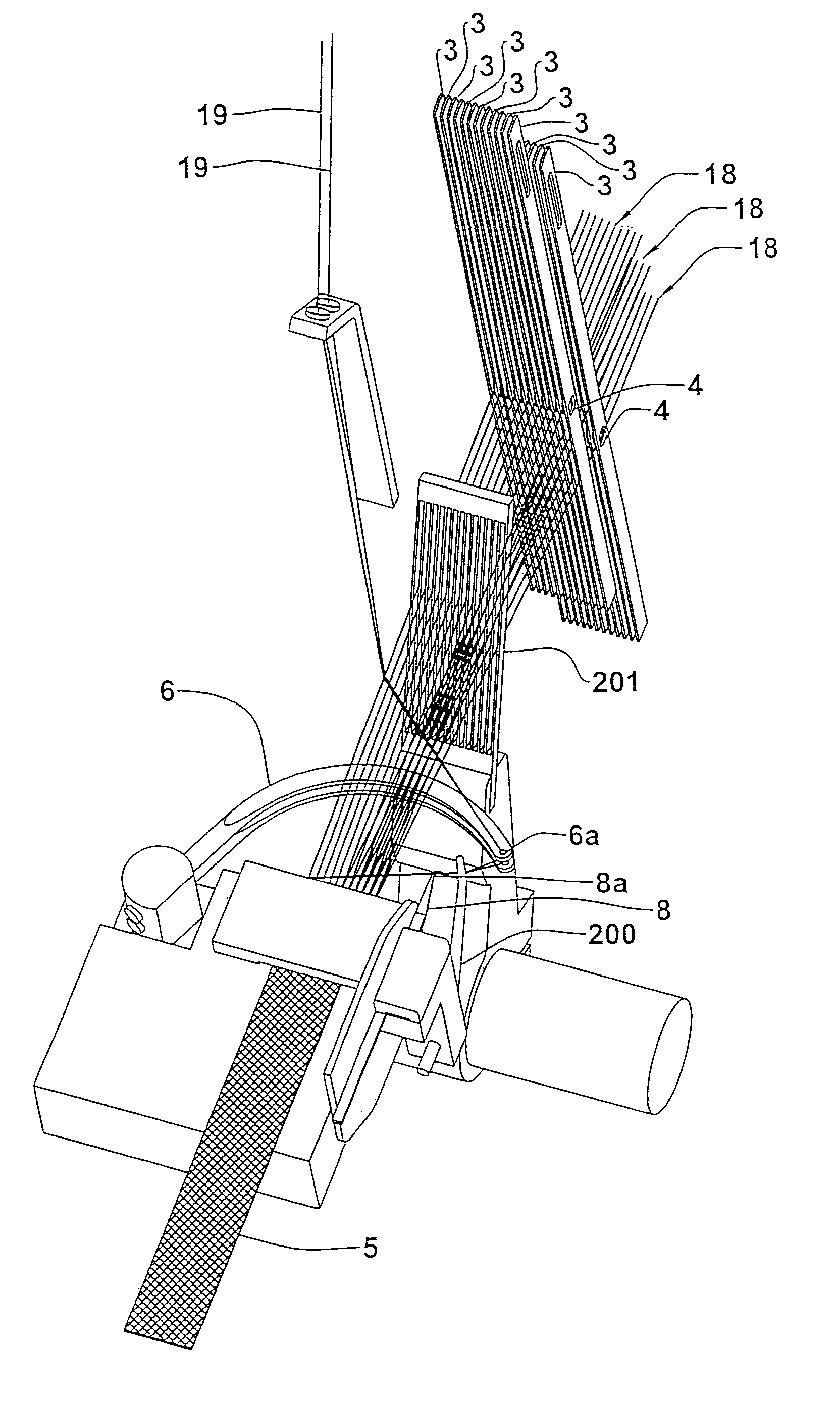
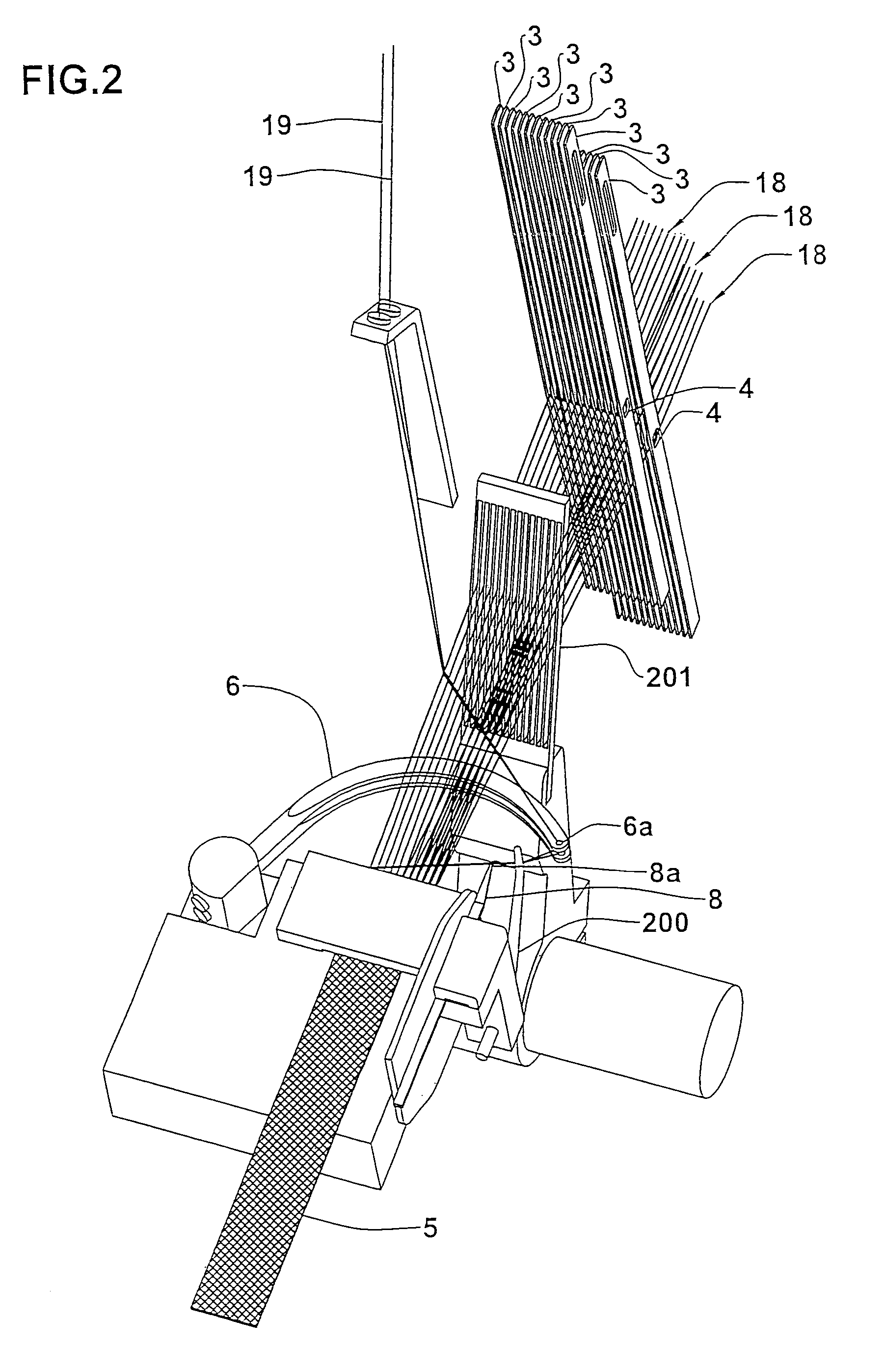
[0029]The textile machine 1 that preferably is a needle loom, comprises a plurality of frames 2, on each of which a plurality of healds 3 is mounted; it is to be noted that in FIG. 1, for the sake of clarity, only a horizontal portion of each frame 2 has been shown.

[0030]Each heald 3 has a slot 4 adapted to engage a respective warp yarn 5. Each frame 2 is moved in a substantially vertical direction, between two or three operating positions; corresponding to each of said operating positions is a different height at which the slots of healds 3 supported by said frame 2 are positioned.

[0031]Frames 2 can be directly connected with the main shaft 12 of loom 1, by means of a cam chain, or they can be moved by electromechanical actuators, suitably operated in accordance with preset programs.

[0032]The machine 1 further comprises at least one s...


PUM


Abstract

A textile machine comprising at least one frame (2) supporting a plurality of healds (3), a sickle (6), a needle (8), a compacting device (201) and a main shaft (12) for a synchronized movement of the frames (2), sickle (6), needle (8) and compacting device (201) and manufacture of a textile product (5); the machine (1) further comprises a first feeding member (20) to supply a plurality of warp yarns (18) to said healds, a second feeding member (40) to supply at least one weft yarn (19) to said sickle and a take-down member (60) of said textile product (5). The machine (1) is also provided with a control apparatus (80) comprising at least one first electromechanical actuator (30) operatively active on said first or second feeding member (20, 40) or on said take-down member (60) for movement of the same, and a controller (90) for regulation of at least said first actuator (30).

Description

FIELD AND BACKGROUND OF THE INVENTION[0001]The present invention relates to a textile machine and the control method thereof.[0002]It is known that in textile machines such as needle looms, among which also the crocheting machines are included, formation of the textile product takes place by mutual interlacing, following predetermined patterns, of a plurality of warp and weft yarns, suitably engaged by respective weaving or knitting members; the latter are for example the healds mounted on one or more heald frames, a predetermined number of sickles and at least one needle.[0003]Also present are auxiliary members such as weft-yarn knocking-over devices and compacting reeds.[0004]These weaving members are operated, through appropriate actuators or kinematic mechanisms of the mechanical type, through synchronized cyclic movements to cause mutual intertwining of the warp yarns and weft yarns following the desired knitting pattern.[0005]The weft yarns are fed to the respective weaving me...

Claims


Application Information

Patent Timeline
Patent Type & Authority Patents(United States)
IPC IPC(8): D03D49/20D03D35/00D03D49/06D03D49/04D03D47/00D03D47/06
CPCD03D35/00D03D49/20D03D49/06D03D47/06
Inventor ZORINI, LUIGI OMODEOFRANCHINO, PIERANTONIO
Owner ZORINI LUIGI OMODEO
Why Eureka
Try Eureka