
Textile machine and control method thereof

a technology of a textile machine and a control method, which is applied in the field of textile machines, can solve the problems of not being able to alter the tensioning of weft and warp yarns, not being able to modify the pulling tension applied, and not being able to have excellent aesthetics

Inactive Publication Date: 2005-03-31
ZORINI LUIGI OMODEO
View PDF6 Cites 4 Cited by
  • Summary
  • Abstract
  • Description
  • Claims
  • Application Information

AI Technical Summary

Benefits of technology

[0018] Another aim of the present invention is to make available a textile machine and the control method thereof that are able to alter tensioning at which the warp yarns are fed to the guide bar, without stopping operation of the machine.
[0019] It is a further aim of the invention to provide a textile machine and the control method thereof that allow the pulling tension of the textile product coming out of the machine to be varied, without stopping operation of the machine.

Problems solved by technology

It is apparent that, taking into account the above described structure and the respective operation modalities, the fabric that is obtained will not be able to have excellent aesthetic features, since the same amounts of weft yarn are employed to make weft rows having different lengths from each other.
Consequently, it is not possible to alter tensioning of the weft and warp yarns when supplied to the respective bars without stopping operation of the machine, neither is it possible to modify the pulling tension applied when the finished product is removed from the front grooved bar.
Therefore, by adopting these modalities of use of the loom it is not possible to alter the fabric compactness or density both in a transverse direction and in a direction parallel to the extension of the textile product, without stopping operation of the machine.
In addition, exactly due to the fact that the warp and weft yarns are fed to the eye-pointed needles and the threading tubes with a constant tension and the textile product is caused to slide between the take-down rollers with a constant tension in time it is not possible to obtain particular aesthetic effects through a controlled variation of the fabric compactness, without stopping operation of the machine, said aesthetic effects comprising alternations of thinner and more compact regions, narrowing or shrinkage of the textile product along a direction substantially perpendicular to the movement direction in which the textile product itself is moved by the take-down rollers, etc.

Method used


Image

  • Textile machine and control method thereof
  • Textile machine and control method thereof
  • Textile machine and control method thereof

Examples


Embodiment Construction

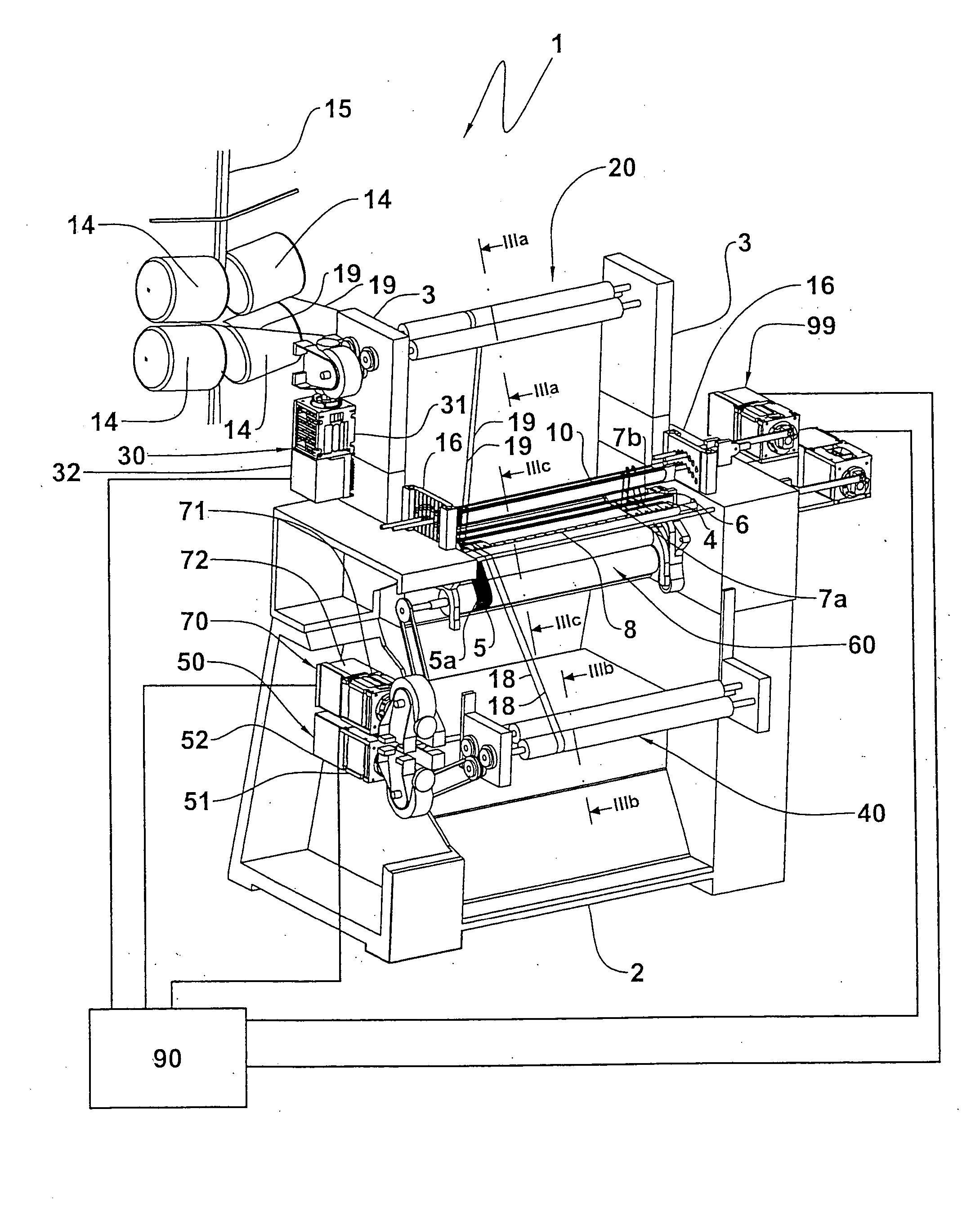
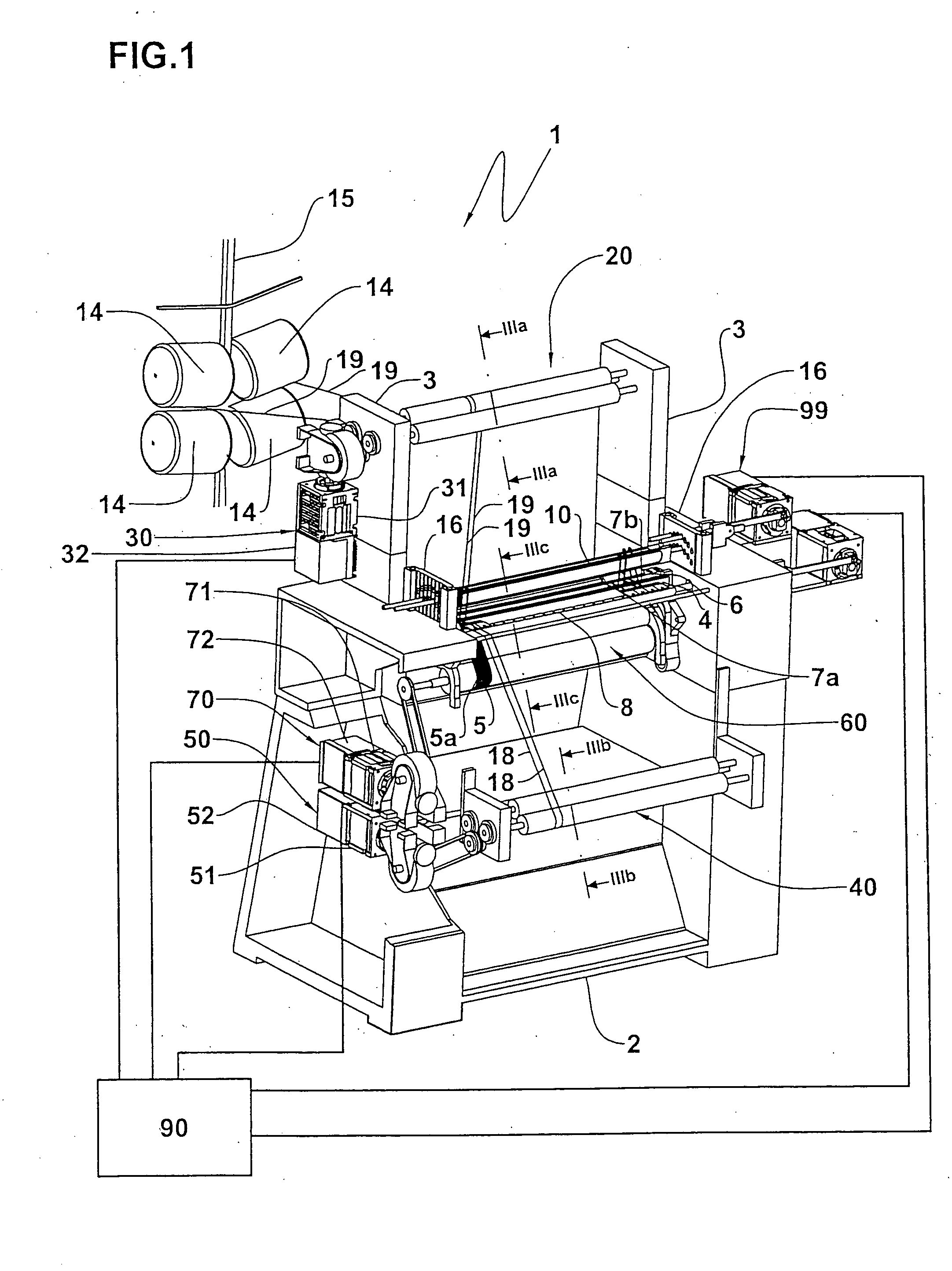
[0030] With reference to the drawings, a textile machine in accordance with the present invention has been generally identified by reference numeral 1.

[0031] The textile machine 1 that is preferably a crochet machine for warp knitting workings comprises a bed 2 provided with two side standards 3, between which at least one front grooved bar 4 horizontally extends, wherein sequential interlacing of the knitting yarns takes place for manufacturing a textile product 5.

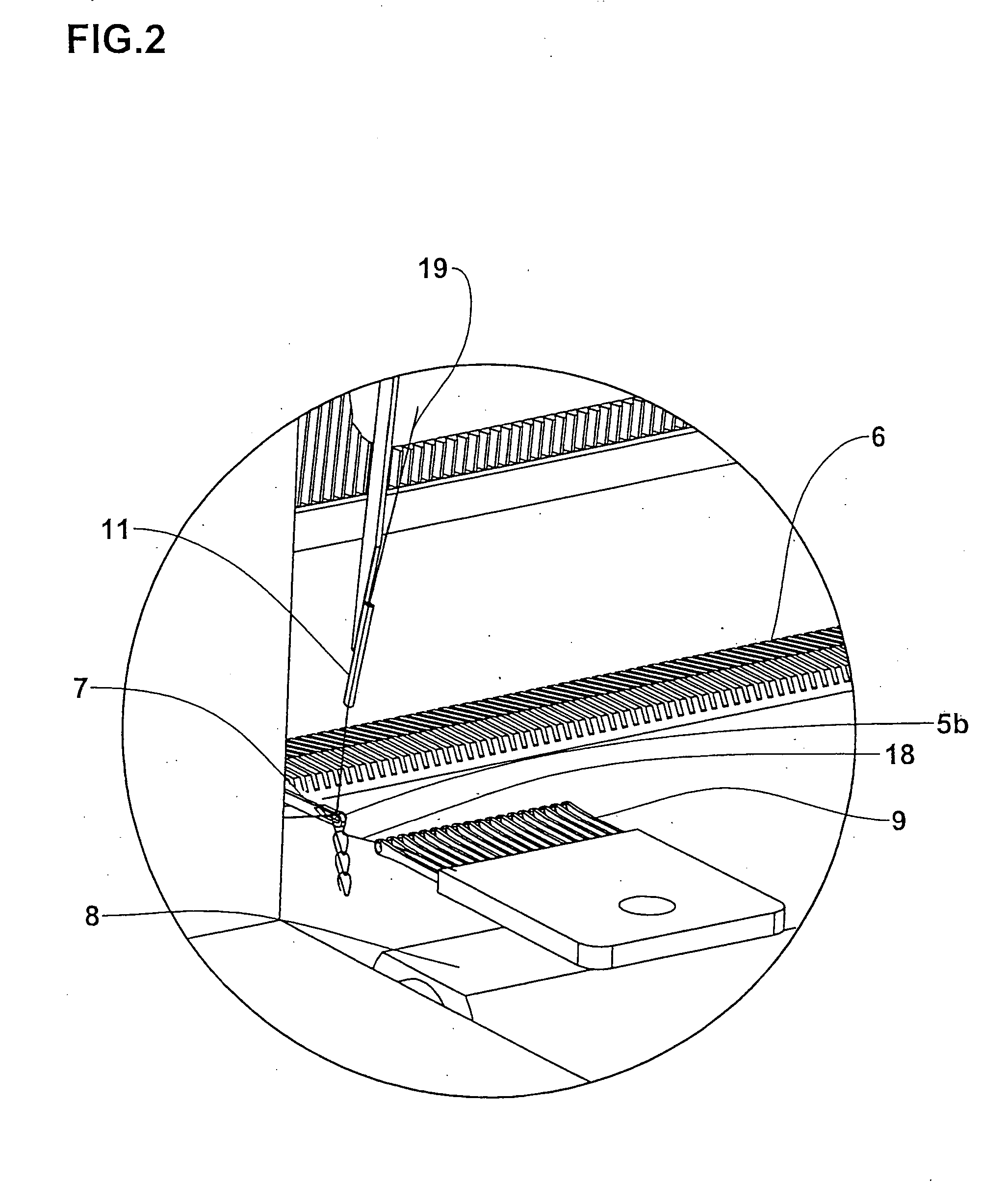
[0032] Also arranged between the side standards 3 is a needle bar 6 supporting a plurality of needles 7; said needles are consecutively aligned with each other along bar 6 and are included between a first needle 7a and a second needle 7b.

[0033] Referring particularly to FIG. 2, the first needle 7a is the first needle starting from the right, whereas the second needle 7b is the first needle starting from the left; for the sake of simplicity other needles are supposed to be present at the right of the first needle 7a or ...


PUM


Abstract

A textile machine comprising a needle bar (6) carrying a plurality of needles (7), a guide bar (8) carrying a plurality of eye-pointed needles (9) and at least one carrier slide bar (10) carrying a plurality of threading tubes (11); the machine (1) further comprises a main shaft (12) for a synchronised movement of the bars (6, 7, 8) and manufacture of a textile product (5), a first feeding member (20) to feed at least one weft yarn (19) to said threading tubes (11), a second feeding member (40) to feed a plurality of warp yarns (18) to said eye-pointed needles (9) and a take-down member (60) to draw said textile product (5). The machine (1) is also provided with a control apparatus (80) comprising at least one first electromechanical actuator (30), operatively active on said first or second feeding members (20, 40) or on said take-down member (60) for movement of same and a controller (90) for regulation of at least said first actuator (30).

Description

FIELD AND BACKGROUND OF THE INVENTION [0001] The present invention relates to a textile machine and the control method thereof. [0002] It is known that in textile machines, such as crochet machines for warp knitting workings, also referred to as crochet galloon looms, formation of the woven product takes place by mutual interlacing, following preestablished patterns, of a plurality of warp and weft yarns, suitably engaged by respective knitting members; said knitting members are for example needles mounted on a needle bar, eye-pointed needles supported by a guide bar and threading tubes mounted on one or more carrier slide bars. [0003] These knitting members are operated by appropriate actuators, with synchronized cyclic movements, to cause mutual interlacing of the warp and weft yarns following the desired knitting pattern. [0004] The weft and warp yarns are fed to the respective knitting members by a plurality of bobbins mounted on a rack-shaped structure called “unwinding creel”,...

Claims


Application Information

Patent Timeline
Patent Type & Authority Applications(United States)
IPC IPC(8): D04B25/12D04B27/10D04B27/34
CPCD04B25/12D04B27/34D04B27/10
Inventor ZORINI, LUIGI OMODEOFRANCHINO, PIERANTONIO
Owner ZORINI LUIGI OMODEO
Learn More