Button knob waterproofing design

a button knob and waterproofing technology, applied in the direction of tumbler/rocker switch details, contact mechanisms, electrical equipment, etc., can solve the problems of increasing the difficulty of providing waterproofing, and increasing the cost of providing waterproofing, so as to improve the durability of waterproofing and prevent waterproofing failure

Inactive Publication Date: 2005-11-08
INVENTEC MULTIMEDIA & TELECOM
View PDF6 Cites 168 Cited by
  • Summary
  • Abstract
  • Description
  • Claims
  • Application Information

AI Technical Summary

Benefits of technology

[0005]In view of the aforesaid problems, the primary object of the invention is to provide a button knob waterproofing design to improve the

Problems solved by technology

Electronic devices are greatly damaged by short circuits in the internal circuitry.
Waterproof and dust-proof functions have become an important design issue.
In general, to provide waterproofing is more difficult since water is a fluid and can infiltrate through very small gaps and slits.
However, waterproofing for the button knob structure on the case surface is more difficult to acco

Method used


Image

  • Button knob waterproofing design
  • Button knob waterproofing design
  • Button knob waterproofing design

Examples


first embodiment

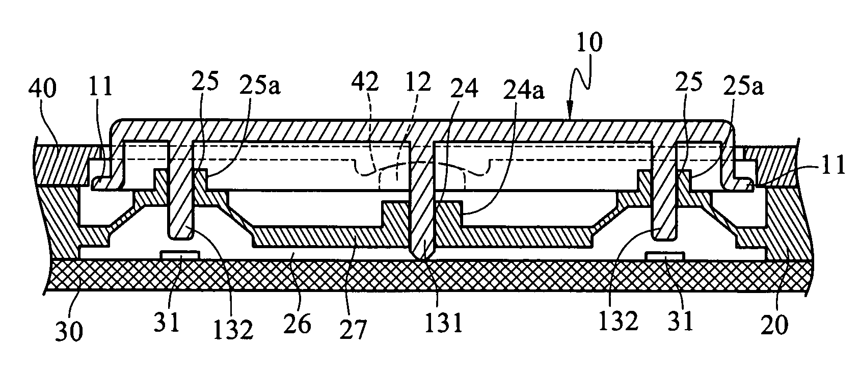
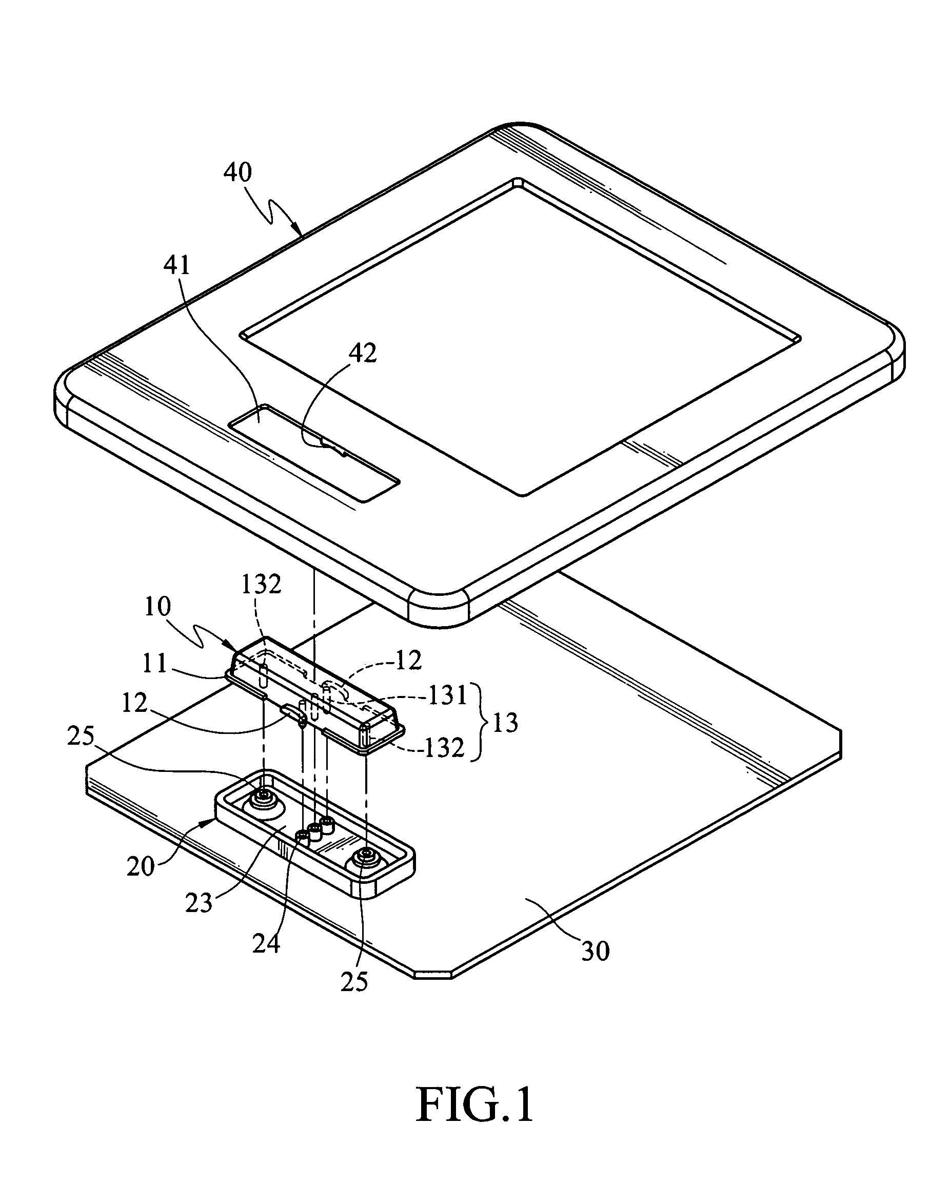
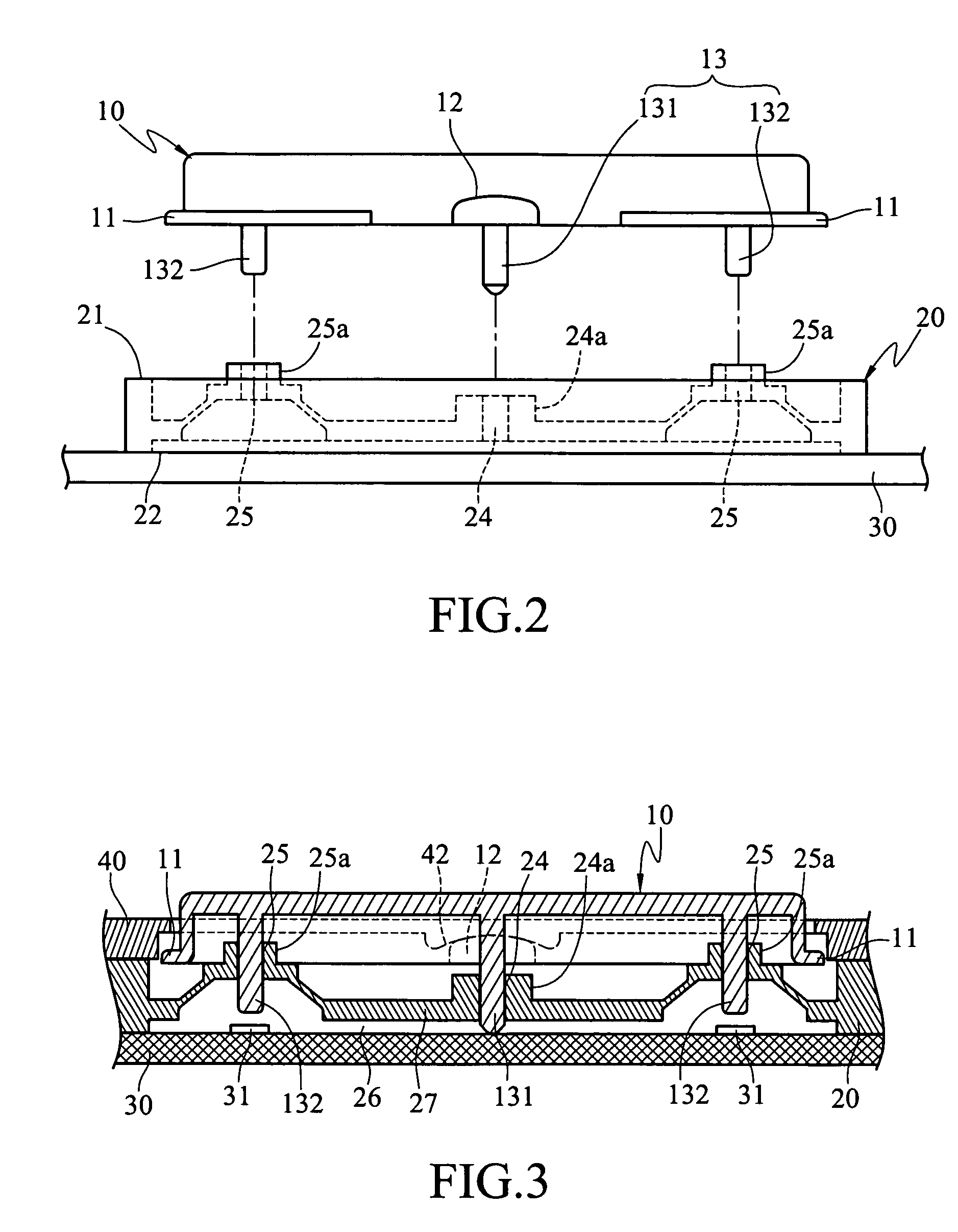
[0014]Refer to FIGS. 1 through 5 for the invention. The button knob waterproofing design according to the invention includes:

[0015]A button cap 10 which is a rectangular box with an opening directing downwards. The button cap 10 has a flange 11 extended horizontally from the bottom edge of an outer wall, two bosses 12 on two long sides that correspond to each other, and a plurality of button stems 13 extending downwards through the opening. The button stems 13 include a first button stem 131 in the center and two second button stems 132 on two ends of the button cap 13. The first button stem 131 is longer than the second button stems 132.

[0016]A button seat 20 made from an elastic material such as rubber. It has a top surface 21 and a bottom surface 22. The top surface 21 has a housing trough 23 to hold the button cap 10. The housing trough 23 has a plurality of apertures including a first aperture 24 and two second apertures 25 on the bottom mating with the button stems and allowin...

second embodiment

[0020]Refer to FIG. 6 for the invention. It includes a button cap 50, a button seat 60, a case 70 and a base board 80.

[0021]The button cap 50 is a hollow box with an opening directing downwards. The button cap 10 has a base 51 and four extensions 52 extended respectively forwards, backwards, to the left and right from the base 51, a plurality of first button stems (not shown in the drawing) on the base 51 and four second button stems (not shown in the drawing) located respectively on the fours extensions 52. The button seat 60 has a top surface and a bottom surface. The top surface has an indented housing trough 61 directing upwards to mate with the button cap 50. The housing trough 61 has a plurality of first apertures 62 and second apertures 63 on the bottom to allow the button stems to pass through. The base board 80 holds the button seat 60 and has a plurality of switches (not shown in the drawing) to be depressed by the second button stems. The case 70 encases the base board 80...


PUM


Abstract

A waterproof button knob includes an elastic button seat with a housing trough mating with a button port of a case. The button seat isolates the interior and the exterior of the case to achieve waterproofing. The housing trough has a plurality of apertures on the bottom. The housing trough holds a button cap that has a plurality of button stems extended downwards to pass through the apertures and form a tight coupling. The button stems may be moved to hit switches located in the case.

Description

FIELD OF THE INVENTION[0001]The invention relates to a button cap and a button knob structure, and particularly to a button knob waterproofing design that has a button cap and a button seat mating and coupling closely to provide waterproofing.BACKGROUND OF THE INVENTION[0002]Electronic devices are greatly damaged by short circuits in the internal circuitry. Hence the casing of the electronic device provides important sealing and shielding functions to protect the internal circuit and prevent dust, moisture or external elements from directly reaching the interior. This also improves the adaptability of the device to varying operational environments, which is especially important for portable devices that are very popular these days. Waterproof and dust-proof functions have become an important design issue. In general, to provide waterproofing is more difficult since water is a fluid and can infiltrate through very small gaps and slits. Once waterproofing is achieved, the problem of f...

Claims


Application Information

Patent Timeline
IPC IPC(8): H01H9/04H01H23/06H01H25/04
CPCH01H23/06H01H25/041
Inventor WENG, SHIH-HSIUNGTEE, KHOON-GUAN
Owner INVENTEC MULTIMEDIA & TELECOM
Why Eureka
Try Eureka