Hallux valgus brace

a brace and valgus technology, applied in the field of hallux valgus brace, can solve the problems of inconvenient walking, inconvenient to wear, and even impossible to wear,

Inactive Publication Date: 2005-11-15
CAMP SCANDINAVIA
View PDF27 Cites 41 Cited by
  • Summary
  • Abstract
  • Description
  • Claims
  • Application Information

AI Technical Summary

Problems solved by technology

The brace bridges the metatarsal joint resulting in that the brace is not suitable for walking because the bending of the joint together with the brace is not comfortable or even impossible.

Method used


Image

  • Hallux valgus brace
  • Hallux valgus brace
  • Hallux valgus brace

Examples


Embodiment Construction

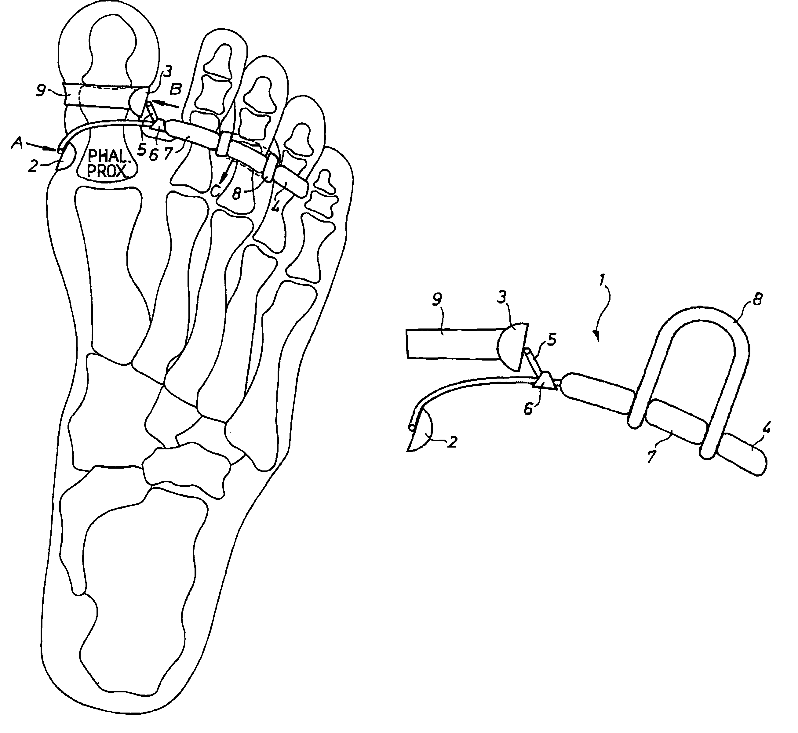
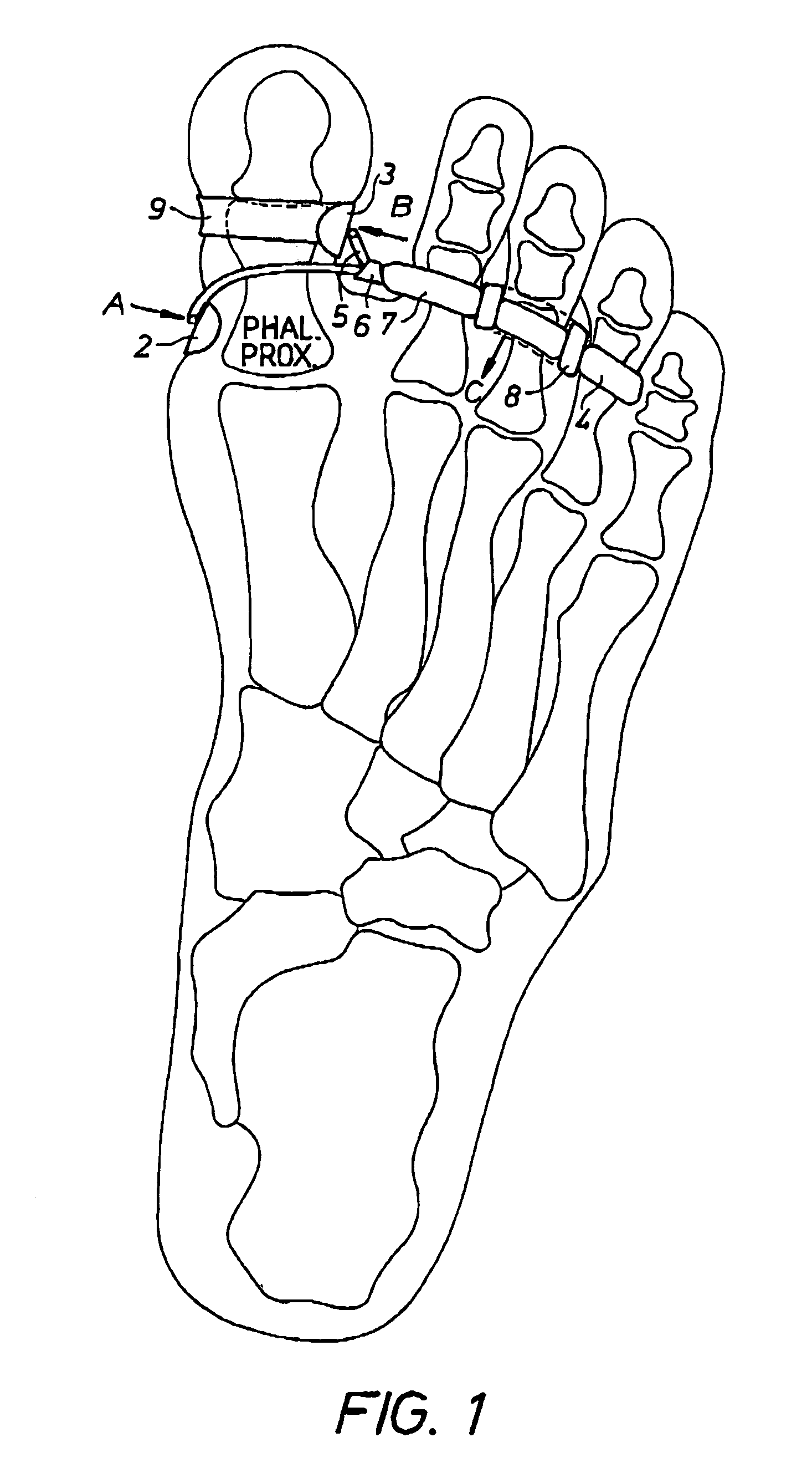
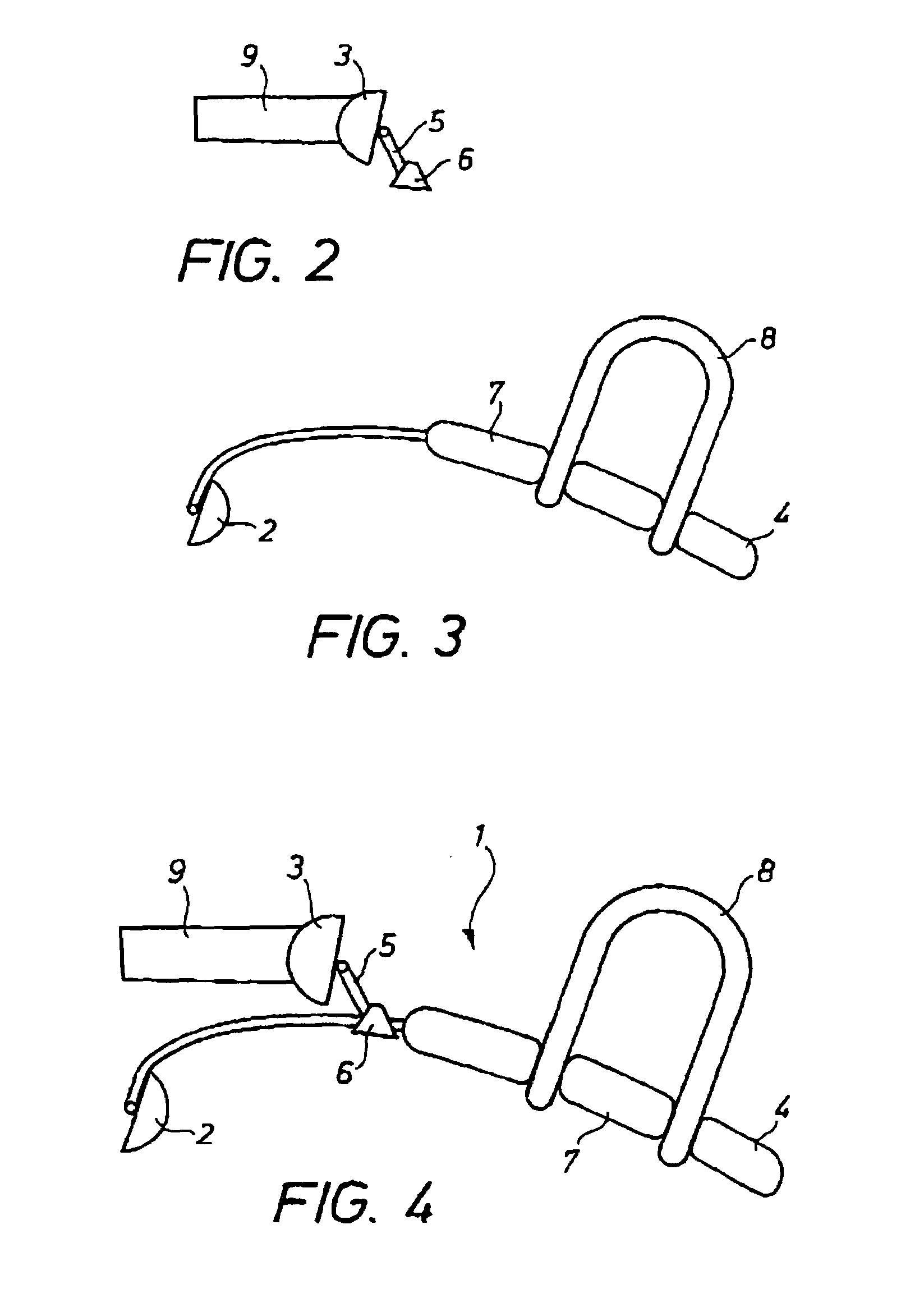
[0012]The hallux valgus brace according to the invention is now described with reference to the drawings. In FIG. 1, the brace is shown as worn by a patient on a foot. The skeletal bones of the foot are shown for reference. In FIG. 4, the complete brace 1 is shown by itself. The brace is located in the space which exists under the normally slightly bent toes. At the medial side the brace carries a proximal pad 2 pressing on the first phalanx of the big toe. A distal pad 3 is carried by an adjustable arm 5 and presses on the distal end of the big toe, preferably on the distal end of the first phalanx.

[0013]The pads 2 and 3 are connected to the frame of the brace by means of hinges, so that the pads can turn and adapt themselves to the curvature of the contact area between the pads and the toe. Thus, the pads 2 and 3 are self-adjusting for better fit and comfort.

[0014]The lateral part of the brace comprises a lever arm 4 pressing backwards and acting as a counterforce on the ball of t...


PUM


Abstract

The invention relates to a hallux valgus brace, i.e. a brace designed for treatment of non-rigid hallux valgus. The brace comprises a three point lever means for correcting the position of the big toe. According to the invention the complete brace is designed to be located distally of the metatarsal joint. Preferably, the brace comprises a proximal pad pressing on the first phalanx of the big toe, a distal pad pressing on the distal end of the first phalanx of the big toe, and a lever arm pressing on the ball of the foot. The brace can be used during walking and other activities.

Description

FIELD OF THE INVENTION[0001]The present invention relates to a hallux valgus brace, i.e. a brace designed for treatment of non-rigid hallux valgus. The complete brace is positioned in front of the metatarsal joint and can be used during walking and other activities.STATE OF THE ART[0002]Hallux valgus is a painful malposition of the big toe, where the big toe turns towards the other toes and a bunion is formed on the protruding joint, i.e. the first metatarsal joint. This deformity has been treated in the past mainly by means of night splints or braces. The brace is mainly used during sleeping or resting. The brace uses three pressure points, two of which are located at the metatarsus. Thus, the prior art brace requires support proximal of the metatarsal joint. The brace bridges the metatarsal joint resulting in that the brace is not suitable for walking because the bending of the joint together with the brace is not comfortable or even impossible.[0003]The present invention solves t...

Claims


Application Information

Patent Timeline
Patent Type & Authority Patents(United States)
IPC IPC(8): A61F5/01A61F5/10A61F13/06
CPCA61F5/019
Inventor SMITS, JAN F. A.
Owner CAMP SCANDINAVIA
Why Eureka
Try Eureka