Insole structure with decompression

a technology of insole structure and compression, which is applied in the direction of soles, insoles, chemistry apparatus and processes, etc., can solve the problems of increased force applied during walking, waste of kinetic energy, and inability to walk on a plane, so as to reduce the pressure of the foot, the effect of high balance and sufficient spa

a technology of insole structure and compression, which is applied in the direction of soles, insoles, chemistry apparatus and processes, etc., can solve the problems of increased force applied during walking, waste of kinetic energy, and inability to walk on a plane, so as to reduce the pressure of the foot, the effect of high balance and sufficient spa

US20200268101A1Inactive Publication Date: 2020-08-27TU HSU TONG

Image

  • Insole structure with decompression
  • Insole structure with decompression
  • Insole structure with decompression

Examples


Embodiment Construction

[0019]Hereinafter, an exemplary embodiment of the present invention will be described in detail with reference to the accompanying drawings.

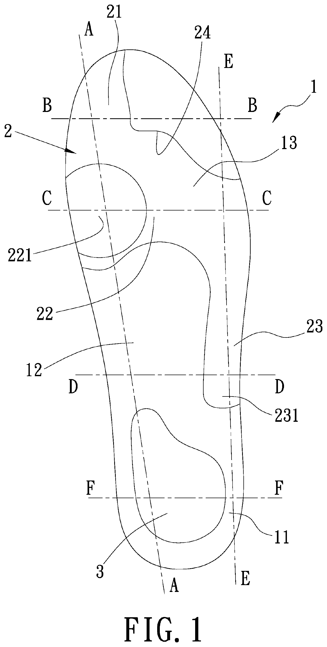
[0020]As showed in FIG. 1, a top view showing an insole structure with decompression according to the present invention is disclosed herein.

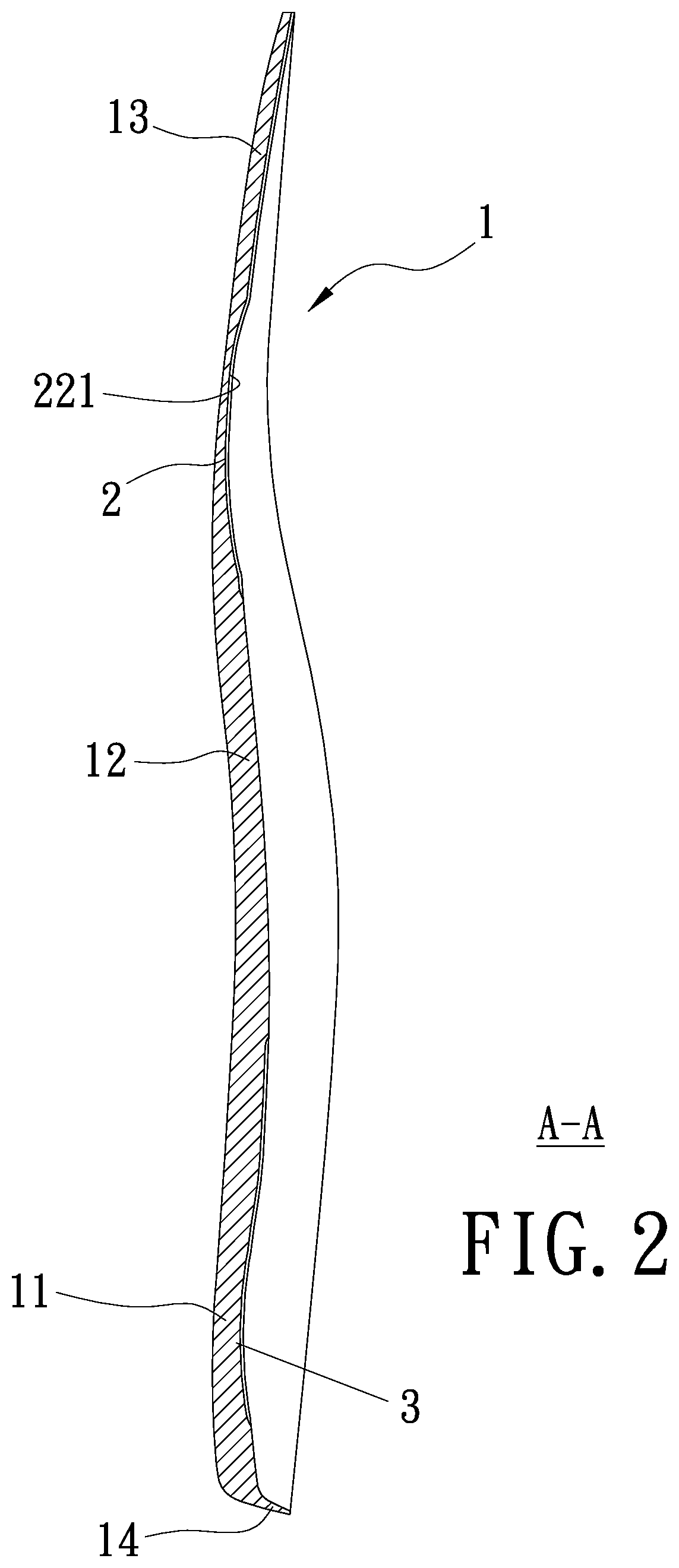
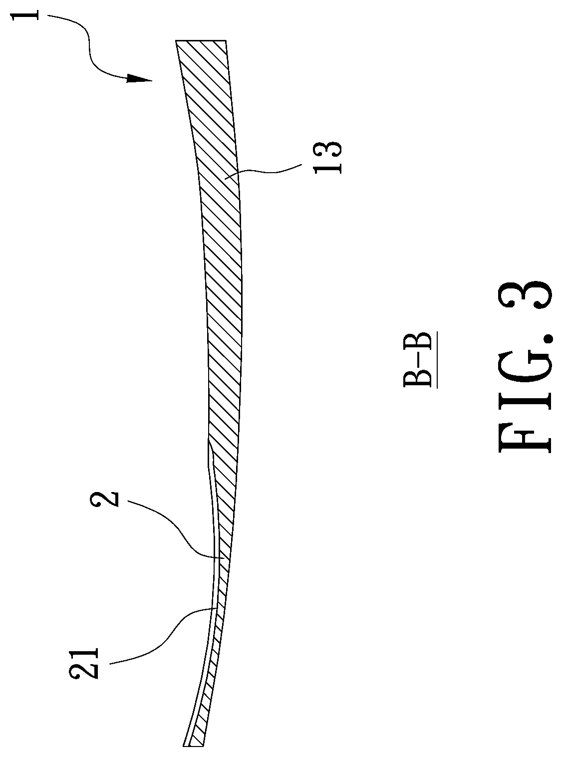
[0021]The insole structure with decompression comprises an insole main body (1), a guiding thin pad portion (2) and a rear thin pad portion (3). The insole main body (1) comprises a heel zone (11), an arch zone (12) and a forefoot zone (13), and a thickness of the insole main body (1) gradually decreases from the heel zone (11) to the forefoot zone (13). The forefoot zone (13) is tilted up. The guiding thin pad portion (2) is disposed between the arch zone (12) and the forefoot zone (13) of the insole main body (1), and the rear thin pad portion (3) is disposed on the heel zone (11) of the insole main body (1).

[0022]Referring to FIG. 1 and FIG. 8, the guiding thin pad portion (2) includes a thumb zone (21) t...


PUM


Abstract

The invention relates to an insole structure with decompression. It comprises an insole main body, and a guiding thin pad portion and a rear thin pad portion disposed on the insole main body, wherein the guiding thin pad portion provides capacity for an area given from metatarsophalangeal joints connected with a first phalanx and a first metatarsal till a fifth phalanx and a fifth metatarsal of the anterior sole, and the rear thin pad portion provides capacity for the calcaneus and have the first metatarsophalangeal joint stay at the lowest place while stepping.

Description

BACKGROUND OF THE INVENTION1. Field of the Invention[0001]The present invention relates to an insole structure with decompression which fits the human feet and smoothly guides the stress dispersion to reduce the pressure of the foot in the walking state or the resting state.2. Description of Related Art[0002]Generally, the insoles attached to the shoes are of uniform thickness, and some are added with a little thickness in the arch area to increase support. Only shoes with higher prices are fitted with hard blocks that secure the foot arch. In areas that are subject to maximum pressure on the heel and forefoot, a cushioning rubber block is also added to prevent the impact from the ground and protect the foot. However, this cushioning rubber block causes resistance during walking, wastes kinetic energy, and increases the force applied during walking.[0003]As shown in FIG. 10, a normal gait flow while walking comprises three steps. First, the feet step out in front of the body and lan...

Claims


Application Information

Patent Timeline
27 Aug 2020
Publication
US20200268101A1
IPC
A43B17/00; A43B17/14; B32B7/12; B32B25/04
CPC
B32B2437/02; B32B7/12; A43B17/14; A43B17/006; B32B2307/744; B32B25/042; A43B7/1425; A43B7/143
Inventors
TU, HSU-TONG