Spray pattern control with non-angled orifices formed on a generally planar metering disc and reoriented on subsequently dimpled fuel injection metering disc

a technology of metering disc and spray pattern, which is applied in the direction of fuel injecting pumps, machines/engines, mechanical equipment, etc., can solve the problems of increasing undesirable exhaust emissions, emissions and driveability problems,

Active Publication Date: 2005-11-22
VITESCO TECH USA LLC
View PDF56 Cites 30 Cited by
  • Summary
  • Abstract
  • Description
  • Claims
  • Application Information

AI Technical Summary

Problems solved by technology

In either case, incomplete combustion may result, leading to an increase in undesirable exhaust emissions.
As a result, a fuel injector designed for a specified cone pattern and targeting of the fuel spray may work extremely well in one type of engine configuration but may present emissions and driveability issues upon installation in a different type of engine configuration.

Method used


Image

  • Spray pattern control with non-angled orifices formed on a generally planar metering disc and reoriented on subsequently dimpled fuel injection metering disc
  • Spray pattern control with non-angled orifices formed on a generally planar metering disc and reoriented on subsequently dimpled fuel injection metering disc
  • Spray pattern control with non-angled orifices formed on a generally planar metering disc and reoriented on subsequently dimpled fuel injection metering disc

Examples


Embodiment Construction

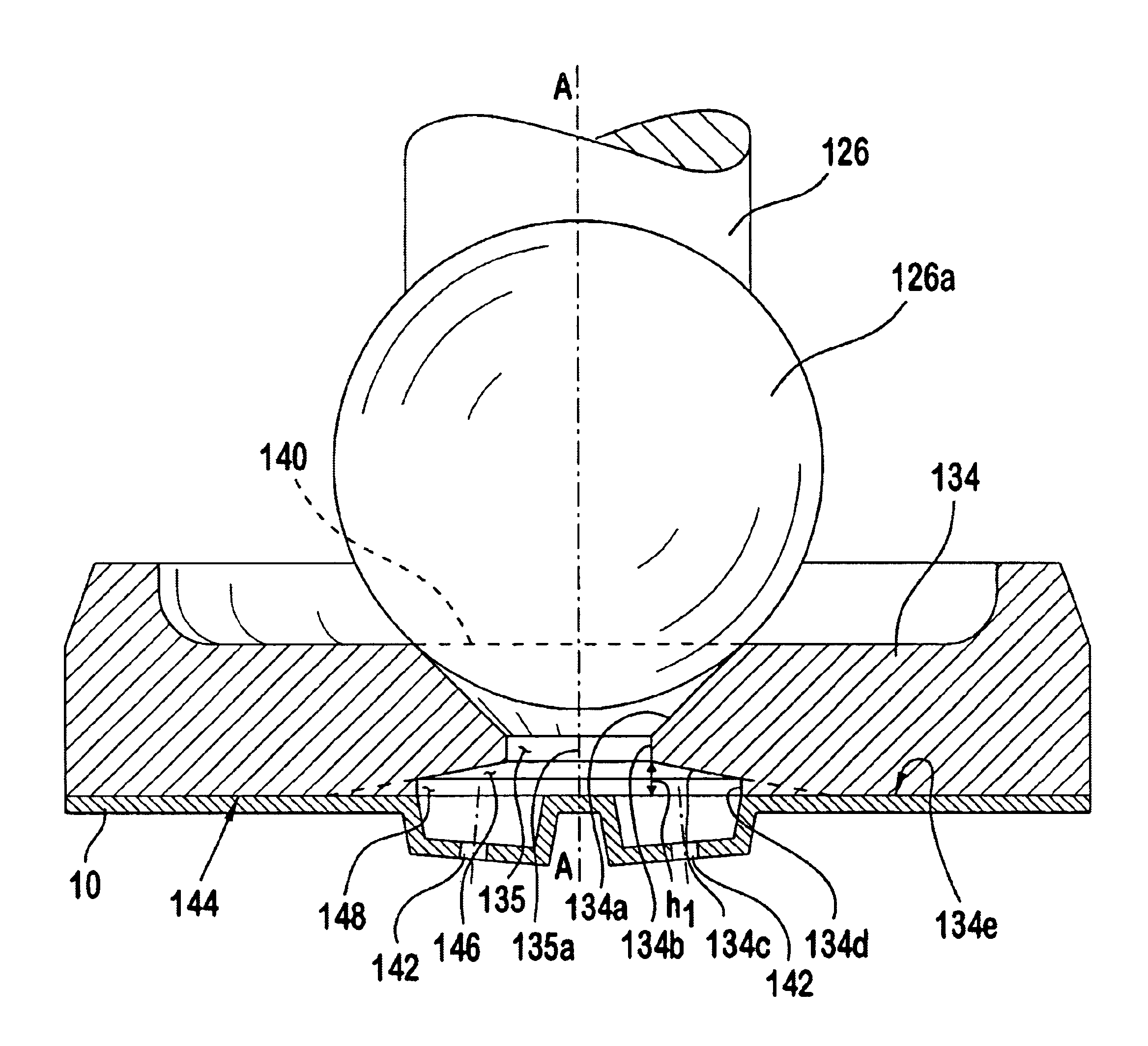
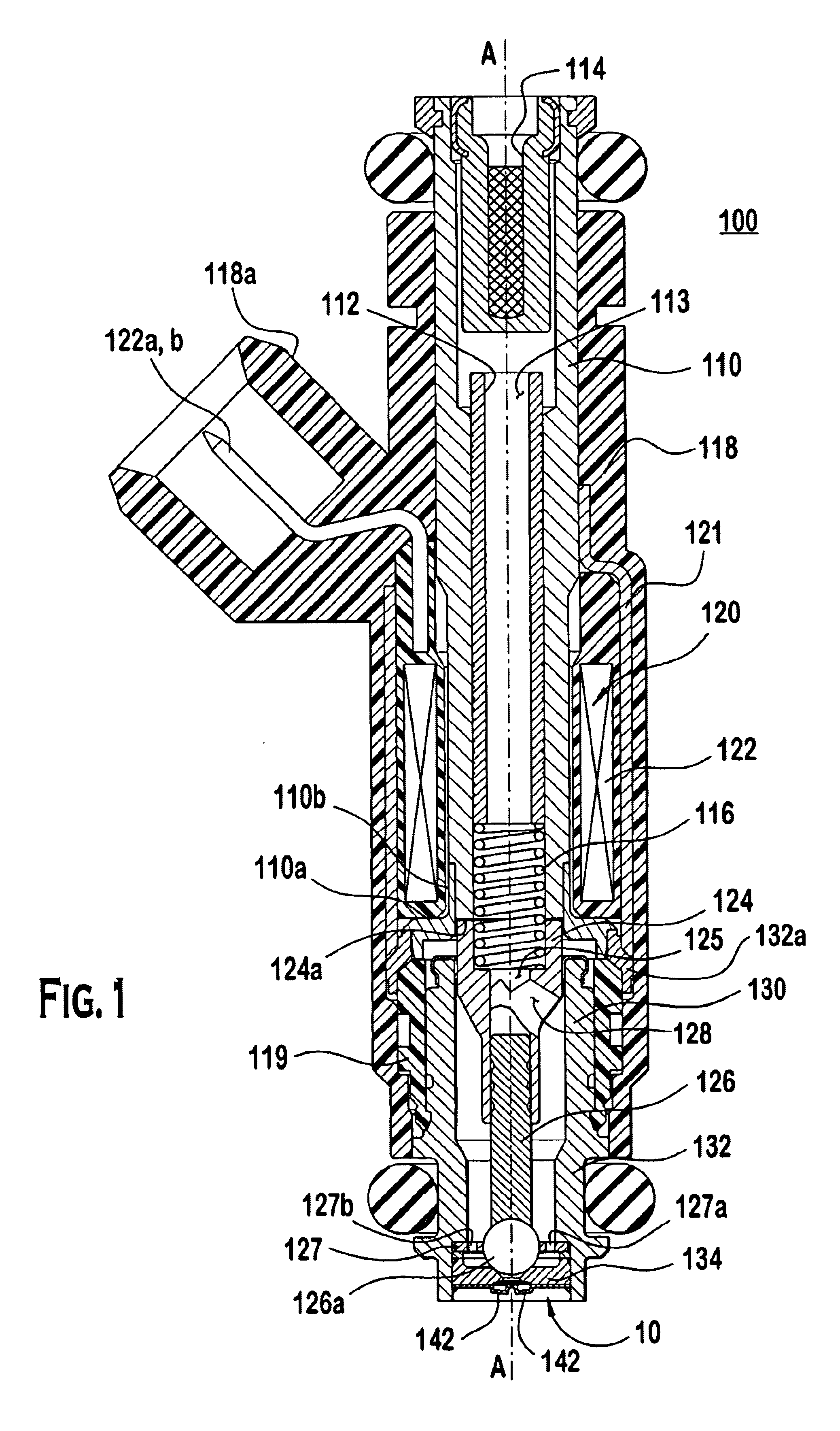
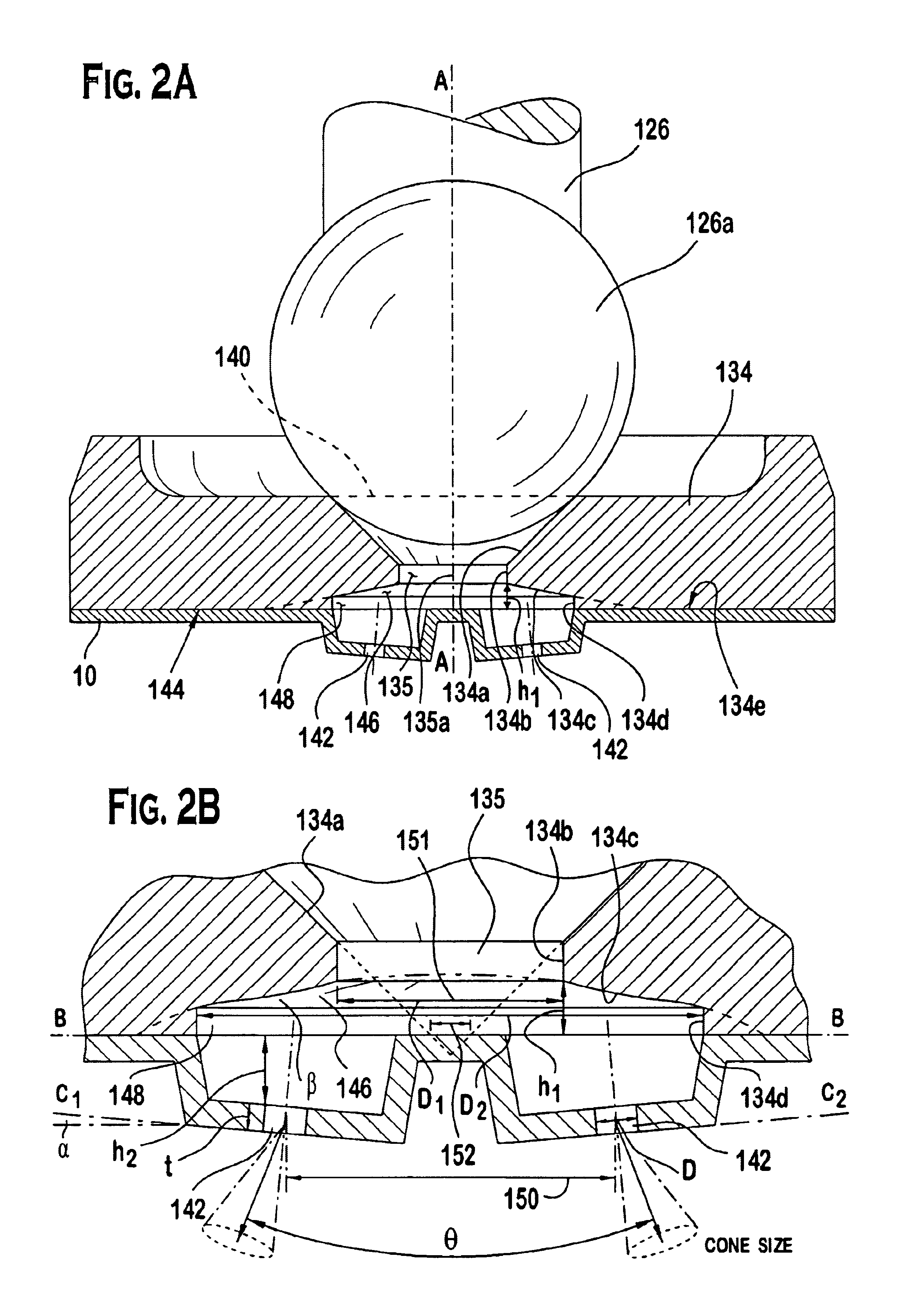
[0021]FIGS. 1-3 illustrate the preferred embodiments. In particular, a fuel injector 100 having a preferred embodiment of the metering disc 10 is illustrated in FIG. 1. The fuel injector 100 includes: a fuel inlet tube 110, an adjustment tube 112, a filter assembly 114, a coil assembly 120, a coil spring 116, an armature 124, a closure member 126, a non-magnetic shell 110a, a first overmold 118, a valve body 132, a valve body shell 132a, a second overmold 119, a coil assembly housing 121, a guide member 127 for the closure member 126, a seat 134, and a metering disc 10.

[0022]The guide member 127, the seat 134, and the metering disc 10 form a stack that is coupled at the outlet end of fuel injector 100 by a suitable coupling technique, such as, for example, crimping, welding, bonding or riveting. Armature 124 and the closure member 126 are joined together to form an armature / needle valve assembly. It should be noted that one skilled in the art could form the assembly from a single co...


PUM


Abstract

A fuel injector that includes a housing, a seat, a metering disc and a closure member. The metering orifices can be located on a first virtual circle greater than a second virtual circle as defined by a projection of a sealing surface converging at a virtual apex projected on the metering disc. The metering disc can be dimpled to increase the spray angle. Various parameters can be utilized to achieve a desired cone size and spray angle. A method of controlling spray targeting of a fuel injector is also described.

Description

PRIORITY[0001]This application claims the benefits of the following United States provisional patent applications:[0002]Ser. No. 60 / 439,059 filed on Jan. 9, 2003, entitled “Spray Pattern Control With Non-Angled Orifices Formed On A Generally Planar Metering Disc And Reoriented On Subsequently Dimpled Fuel Injection Metering Disc”;[0003]Ser. No. 60 / 438,952, filed on Jan. 9, 2003 entitled “Spray Pattern Control With Non-Angled Orifices Formed On A Dimpled Fuel Injection Metering Disc Having A Sac Volume Reducer”;[0004]Ser. No. 60 / 439,094 filed on Jan. 9, 2003, entitled, “Spray Pattern Control With Non-Angled Orifices Formed On Dimpled Fuel Injection Metering Disc Having A Sac Volume Reducer,” which provisional patent applications are herein incorporated by reference in their entirety in this application.BACKGROUND OF THE INVENTION[0005]Most modern automotive fuel systems utilize fuel injectors to provide precise metering of fuel for introduction into each combustion chamber. Additiona...

Claims


Application Information

Patent Timeline
Patent Type & Authority Patents(United States)
IPC IPC(8): F02M61/00F02M61/16F02M61/18F02M51/06F02M63/00
CPCF02M51/0653F02M51/0671F02M61/1806F02M61/1846F02M61/1853F02M61/165F02M2200/505Y10S239/90
Inventor NALLY, JOHN F.PETERSON, JR., WILLIAM A.
Owner VITESCO TECH USA LLC
Why Eureka
Try Eureka