Cable and method

a technology of cable and cable, applied in the field of cable, can solve the problems of loosening of the connection, affecting the flexibility of the cable, and affecting the service life of the cable,

Inactive Publication Date: 2005-11-29
LOCKHEED MARTIN CORP
View PDF28 Cites 17 Cited by
  • Summary
  • Abstract
  • Description
  • Claims
  • Application Information

AI Technical Summary

Problems solved by technology

Such attachments may, over time, loosen due to cable flexure or to vibrations imposed on the cable as a result of the environment in which the cables are used.
Further, such cables tend to be large in diameter if they contain large numbers of conductors, which may impair the flexibility of the cable.
These types of cables may also be heavy, which may be less desirable in applications such as aircraft, missiles, or the like where weight is a prime design factor.
However, such cables are generally limited in the number of conductors that they may contain.
Further, it may be difficult to shield this type of cable from aggressive electromagnetic interference (“EMI”).
Lengths for such cables have traditionally been limited to the size of the panel being used as raw material in the process.
Such cables have been generally limited to a single substrate, as described above, due to the sharpness of the fold.
Thus, these cables are also limited in the number of conductors that they may include.

Method used


Image

  • Cable and method
  • Cable and method
  • Cable and method

Examples


first embodiment

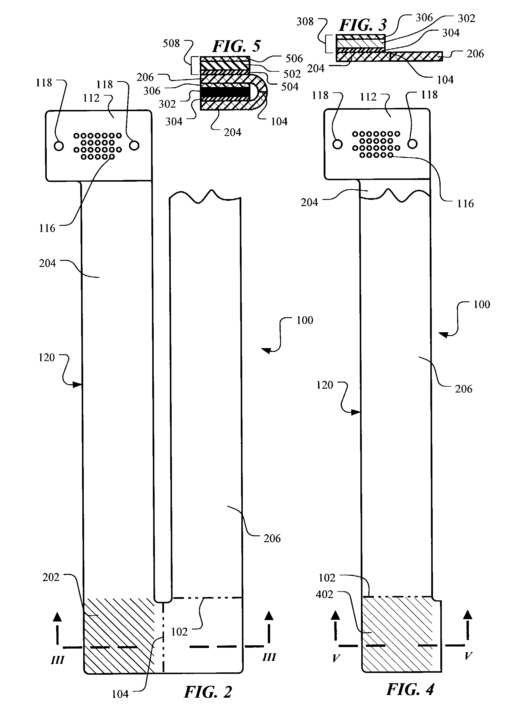
[0050]According to the present invention, the cable 100 may be folded into an elongated form as illustrated in FIGS. 2–7. Referring to FIGS. 2 and 3, a first shim 302 is adhesively bonded to an area 202 (indicated by hatching) of the intermediate portion 120 by a first layer of adhesive 304. A second layer of adhesive 306 is then applied to the first shim 302. Alternatively, a shim assembly 308 having adhesive layers 304, 306 that have been pre-applied to the first shim 302 may be used. In this situation, the shim assembly 308 may be applied as a unit to the area 202 of the intermediate portion 120. The intermediate portion 120 is then folded along the fold line 104 so that a second leg 206 may be placed into contact with the second adhesive layer 306, thus adhesively bonding the second leg 206 to the first shim 302, as illustrated in FIGS. 4 and 5.

[0051]Still referring to FIGS. 4 and 5, a second shim 502 is bonded to an area 402 (indicated by hatching) of the intermediate portion 1...

second embodiment

[0056]Alternatively, it may be desirable to decrease the number of shims over the embodiment illustrated in FIGS. 2–7. Thus, according to the present invention, the cable 100 may be folded into an elongated form as illustrated in FIGS. 11–16. Referring to FIGS. 11 and 12, a shim 1202 is bonded to an area 1102 (indicated by hatching) of the intermediate portion 120 by a first layer of adhesive 1204. A second layer of adhesive 1206 is then applied to the shim 1202. Alternatively, a shim assembly 1208 having adhesive layers 1204, 1206 that have been pre-applied to the shim 1202 may be used. In this situation, the shim assembly 1208 may be applied as a unit to the area 1202 of the intermediate portion 120. The intermediate portion 120 is then folded along the fold line 105 so that a first leg 204 is placed into contact with the second adhesive layer 1206, thus adhesively bonding the first leg 204 to the shim 1202, as illustrated in FIGS. 13 and 14.

[0057]Still referring to FIGS. 13 and 1...

third embodiment

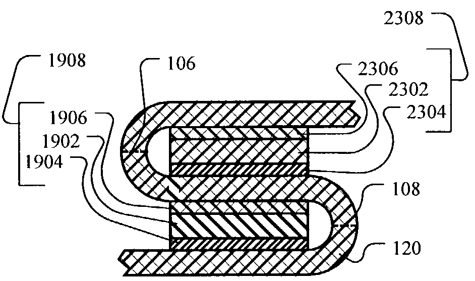
[0061]It may be desirable in certain situations to fold the cable 100 diagonally, rather than generally perpendicular to the side edges of the cable 100. Thus, according to the present invention, the cable 100 may be folded into an elongated form as illustrated in FIGS. 18–25. Referring to FIGS. 18 and 19, a first shim 1902 is bonded to an area 1802 (indicated by hatching) of the intermediate portion 120 by a first layer of adhesive 1904. A second layer of adhesive 1906 is then applied to the first shim 1902. Alternatively, a shim assembly 1908 having adhesive layers 1904, 1906 that have been pre-applied to the first shim 1902 may be used. In this situation, the shim assembly 1908 may be applied as a unit to the area 1802. The intermediate portion 120 is then folded along the fold line 108 so that a third leg 1804 may be placed into contact with the second adhesive layer 1906, thus adhesively bonding the third leg 1804 to the first shim 1902, as illustrated in FIGS. 20 and 21.

[0062]...


PUM

PropertyMeasurementUnit
thicknessaaaaaaaaaa
pressure-sensitiveaaaaaaaaaa
pressureaaaaaaaaaa

Abstract

A cable includes a first portion, a second portion, and a first fold between the first portion and the second portion. The cable further includes a first shim bonded between the first portion and the second portion. A method for making a cable includes adhesively bonding a first surface of a first shim to a first surface of the cable, folding the cable over the first shim, and adhesively bonding the first surface of the cable to a second surface of the first shim. A method includes folding a cable and adhesively bonding a shim in the fold to the interior surfaces defined by the fold.

Description

BACKGROUND OF THE INVENTION[0001]1. Field of the Invention[0002]This invention relates to a cable and its method of manufacture and, more particularly, to a folded cable and its method of manufacture.[0003]2. Description of the Related Art[0004]Cables generally are used as pathways for transmitting signals to and from equipment. For example, an electrical cable or an optical fiber cable may interconnect two computers so that data may be shared between the computers. Signals corresponding to the data to be shared are transmitted via conductors (e.g., electrical conductors or fiber optic conductors) within the cable. Conductors within cables may also be used as pathways to supply power to equipment.[0005]Historically, such cables have been made of individual conductors arranged in a generally round bundle and sheathed by shielding and / or insulating jackets. Ends of the conductors may be soldered, crimped, or otherwise mechanically attached to connectors that mate with connectors on th...

Claims


Application Information

Patent Timeline
Patent Type & Authority Patents(United States)
IPC IPC(8): H01B7/08H01B13/012H01R4/04
CPCH01R4/04H01R12/61
Inventor DUPRIEST, CHARLES DONALD
Owner LOCKHEED MARTIN CORP
Why Eureka
Try Eureka