Automotive wheel assembly removal apparatus

a technology for removing apparatuses and wheels, applied in metal working apparatuses, metal-working apparatuses, manufacturing tools, etc., can solve the problems of increasing maintenance costs, requiring replacement parts, and generally ineffective methods for combating severe corrosion of parts, so as to maximize load distribution, minimize the potential for damage to engagement members, and maximize kinetic energy and load transfer efficiency

Inactive Publication Date: 2005-12-06
WEST CENT OHIO TOOL DISTRIBUTORS
View PDF15 Cites 9 Cited by
  • Summary
  • Abstract
  • Description
  • Claims
  • Application Information

AI Technical Summary

Benefits of technology

[0012]Additional embodiments of the interchangeable rotor securing tool are adapted so that the tool can be securely coupled to the rim mounting surface to transfer a substantially axial impact load approximately uniformly to the rim mounting surface. This modification may be used with any of the preceding embodiments and incorporates an interchangeable rotor securing tool that is adapted to be in contact with a substantial portion of the rim mounting surface, rather than being limited to engaging only one engagement member. Then, with the engagement members received through one of the engagement hole patterns and fastened to the tool, the slide shaft is preferably applied to be approximately orthogonal to the rim mounting surface and will transfer substantially axial operational impact loads. While it is preferably that all the engagement members be fastened to the tool to maximize the load distribution and minimize the potential for damaging the engagement members, the apparatus can function when fastened to at least one engagement member. Additionally, the substantial amount of contact area between the rim mounting surface and the tool, when properly connected, ensures a substantially distributed load transfer interface for the uniform transfer of separation impact loads from the tool to the rim mounting surface.
[0013]Further, the apparatus also preferably can include a support extension at the distal end of the slide shaft. The support extension allows the operator to rest the distal end of the apparatus on a support device during setup and operation, such as a jack stand. Therefore, the operator does not have to support the weight of the apparatus during setup or while in use. Additionally, with the support extension on a jack stand, the operator can ensure that the slide shaft is generally orthogonal to the plane of the rim mounting surface to maximize kinetic energy and load

Problems solved by technology

This method does not evenly distribute the pulling forces to the wheel assembly and often results in damage to the engagement members and the wheel assembly, which can require replacement parts and increased maintenance costs.
However, this method is generally ineffective to combat severely corroded parts and is generally incompatible for use with most OEM vehicle configurations such as, for example, four-wheel drive vehicles that incorporate complex axle locations.
As a result of such difficulty and in light of the expense and ineffectiveness of most prior art devices, mechanics generally resort to the hammer and mallet methods typically impart unevenly applied impact forces, which often damage the hub, rotor, bearings, axle, and spindle.
As noted above, the problem of seized wheel assembly components is especially common in load carrying vehicles.
Removing the seized components of load carrying vehicles can take dozens of forceful hammer blows to the rotor, and often requires the use of a torch.
This traditional removal technique is dangerous, time cons

Method used


Image

  • Automotive wheel assembly removal apparatus
  • Automotive wheel assembly removal apparatus
  • Automotive wheel assembly removal apparatus

Examples


Embodiment Construction

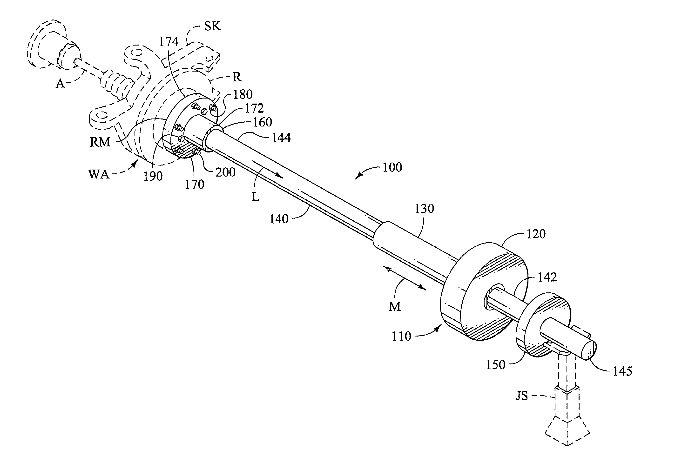
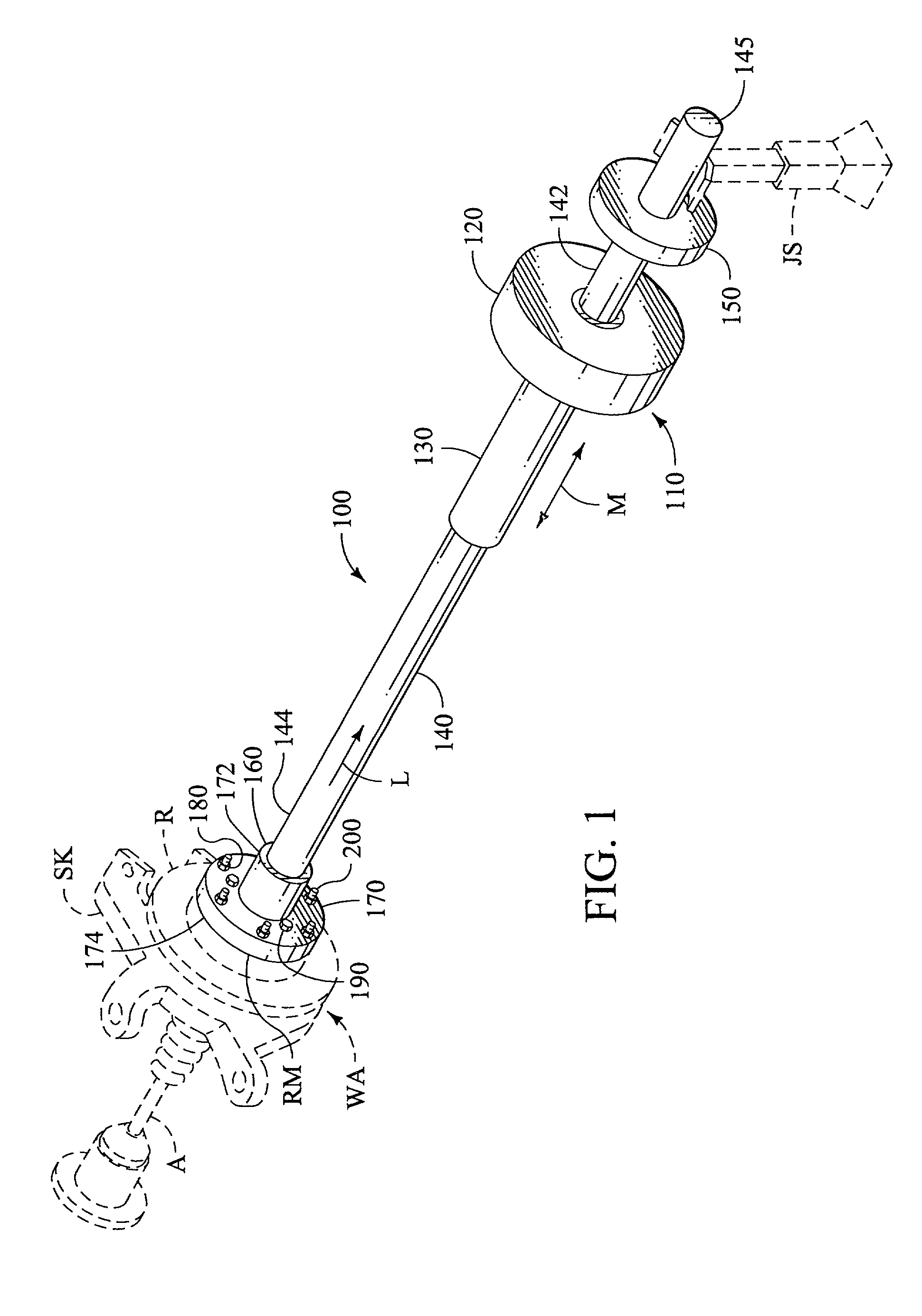
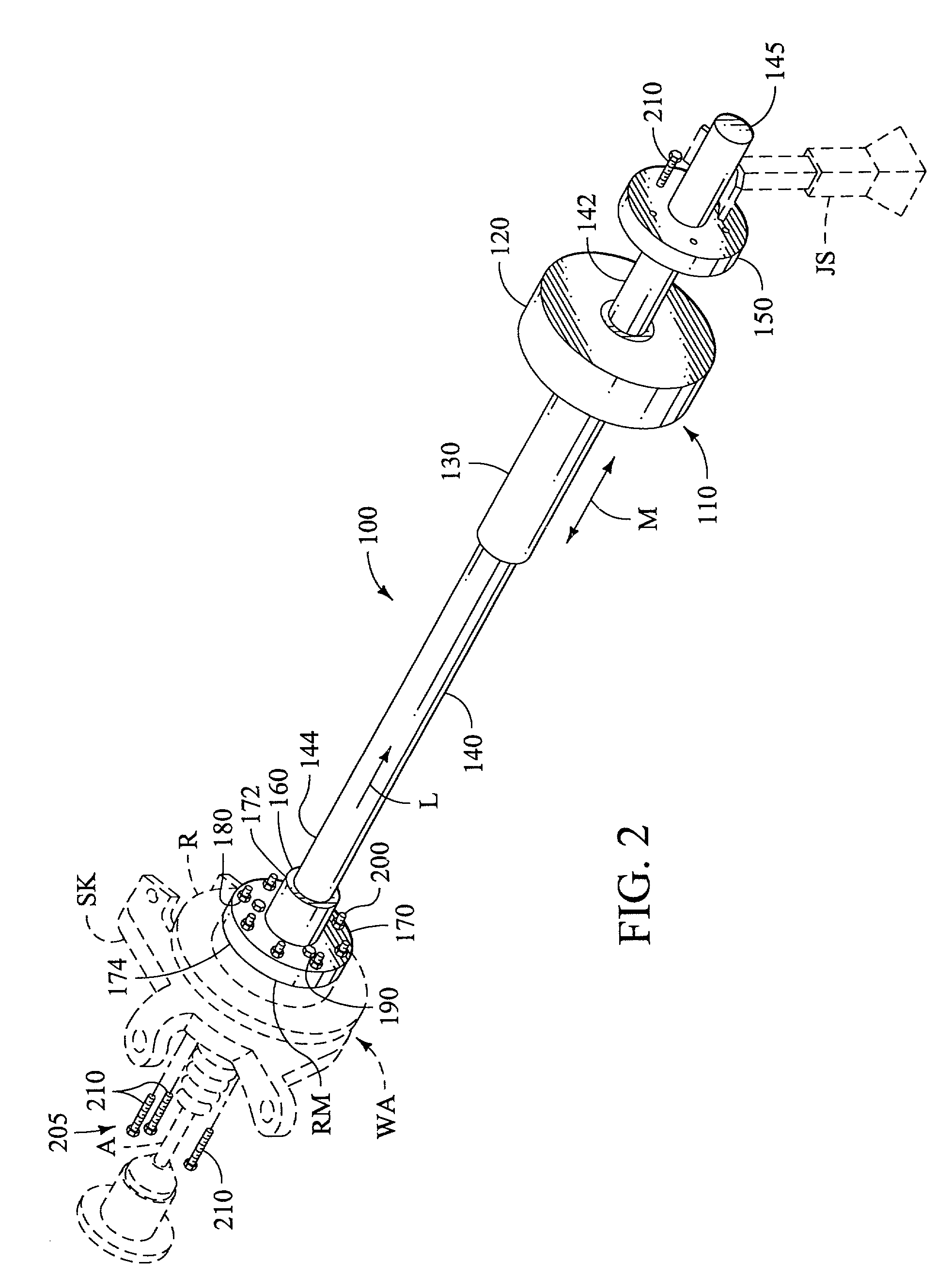
[0025]The wheel assembly removal apparatus according to the present invention demonstrates a significant step forward in the field of vehicle maintenance tools, and more specifically in the field of wheel assembly removal tools. Many undesirable, ineffective, and unsuccessful attempts have been made to create a wheel assembly removal apparatus having the convenience and efficiency of the present invention. The preferred wheel assembly removal apparatus has wide application for all wheel based vehicles that incorporate wheel or rotating assemblies that are subject to removal for maintenance and replacement. The preferred configurations and described alternatives, modifications, and variations of the wheel assembly removal apparatus of the instant invention overcome prior shortcomings and accomplish new and novel solutions to the prior art problems with vastly improved configurations and arrangements of inventive elements that are uniquely configured, and which demonstrate previously ...


PUM

PropertyMeasurementUnit
Momentumaaaaaaaaaa
Flexibilityaaaaaaaaaa

Abstract

A wheel assembly removal apparatus for use in the automotive maintenance and repair industry. The apparatus is adapted to remove a seized wheel assembly, and associated components, from a vehicle chassis for maintenance and repair while minimizing time and cost, and the possibility for damage. The wheel assembly removal apparatus preferably incorporates, among other elements, a slide hammer assembly that includes a hammer secured to a hollow slide tube. The hollow slide tube is received on a slide shaft. The slide shaft also preferably incorporates a hammer stop near a distal end and a distally projecting support extension. A coupler is formed at a proximal end of the slide shaft and is configured to releasably engage an interchangeable rotor securing tool. The interchangeable rotor securing tool releasably attaches to the coupler at the distal end and to a rim mounting surface at the proximal end. In operation, the slide hammer assembly is accelerated from the proximal end of the slide shaft to impact with the hammer stop, which creates linear momentum transfer in the form of an operational impact load. The impact load is transferred to the wheel assembly to break free the various components that may be seized together from the accumulation of dirt, dust, moisture, and corrosion. The apparatus includes at least one releasably engagable retainer assembly to loosely retain the wheel assembly to the vehicle chassis for controlled separation of the seized components. The apparatus may also preferably include a dual hand operation mechanism.

Description

TECHNICAL FIELD[0001]This invention relates to tools and particularly to a tool adapted to remove a wheel assembly from a vehicle chassis for automotive maintenance and repair. More specifically, the invention relates to a durable, inexpensive, and reconfigurable apparatus for removal of the wheel assembly from the vehicle chassis of a plurality of original equipment manufacturer (hereafter also referred to as “OEM”) product linesBACKGROUND OF THE INVENTION[0002]In the various automotive vehicle industries, including for purposes of illustration but not limitation, wheel and brake servicing and repair, those with skill in the art have long-recognized the need for an improved method of removing the various components of a wheel assembly without damage, including, for example, the rotors, hubs, bearings, spindles, and axles.[0003]In the past, mechanics have had to resort to blow torches, mallets, hammers, and the like to remove and break free the various components that may be seized ...

Claims


Application Information

Patent Timeline
IPC IPC(8): B25B27/02
CPCB25B27/02Y10T29/53839
Inventor BERMAN, THEODORE J.HUELSMAN, JOHN C.BERGMAN, JON E.
Owner WEST CENT OHIO TOOL DISTRIBUTORS
Why Eureka
Try Eureka