
Interconnect device with opposingly oriented contacts

a technology of opposing orientation and interconnection, which is applied in the direction of coupling contact members, coupling device connections, multiple conductor connectors, etc., can solve the problems of limiting the alignment of parts, deflection range and cost, and losing the cleaning action of the wipe action

Active Publication Date: 2005-12-06
TELEDYNE
View PDF9 Cites 25 Cited by
  • Summary
  • Abstract
  • Description
  • Claims
  • Application Information

AI Technical Summary

Benefits of technology

This configuration effectively reduces cumulative sideways wipe forces, maintaining alignment and cost-effectiveness while meeting small dimensional requirements, enhancing manufacturing simplicity and reducing the need for robust alignment techniques.

Problems solved by technology

This can be problematic.
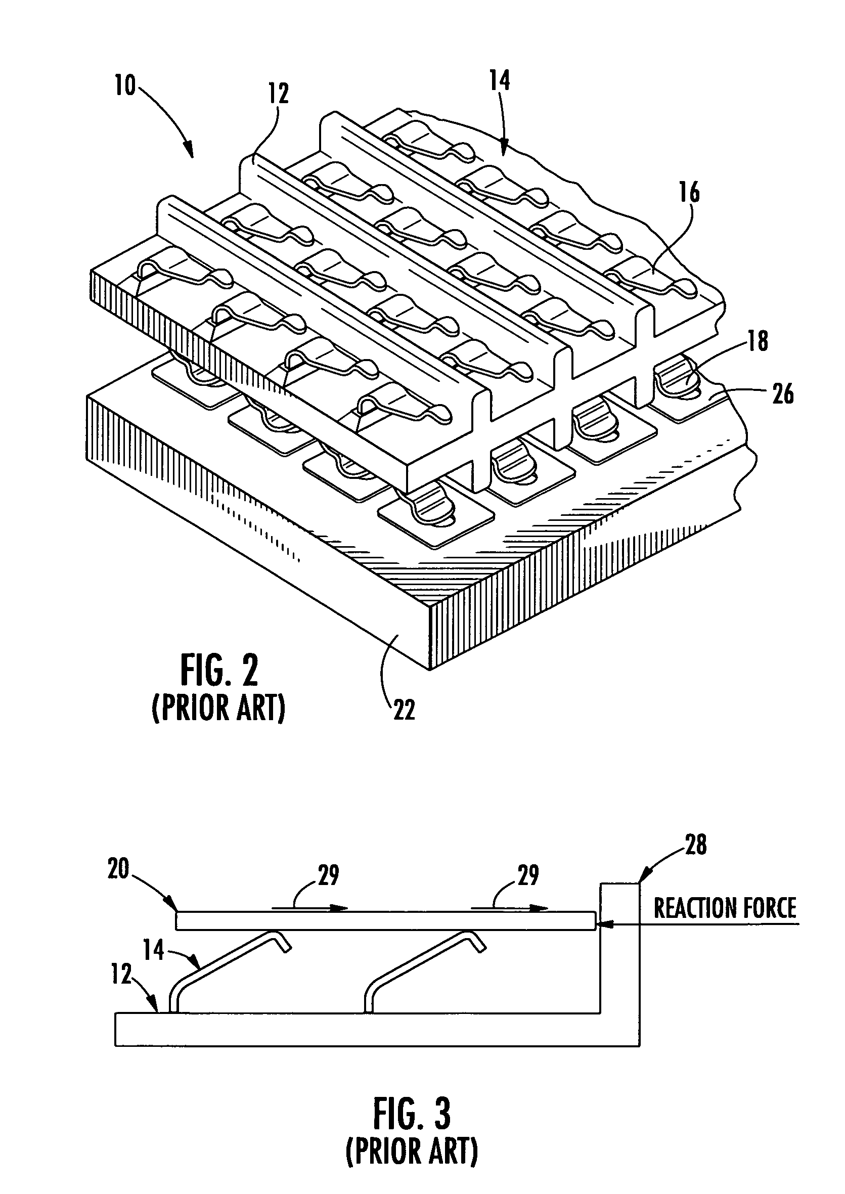
Such a large wipe force limits how the parts can be kept in alignment because many alignment techniques cannot withstand such large sideways wipe forces.
Such contacts, however, lose the cleaning action that the wipe action provides.
Other drawbacks of such contacts include deflection range and cost.
While such techniques may be acceptable for some applications, such large sidewalls and / or alignment pins can present space and tolerance problems in other applications.

Method used


Image

  • Interconnect device with opposingly oriented contacts
  • Interconnect device with opposingly oriented contacts
  • Interconnect device with opposingly oriented contacts

Examples


Embodiment Construction

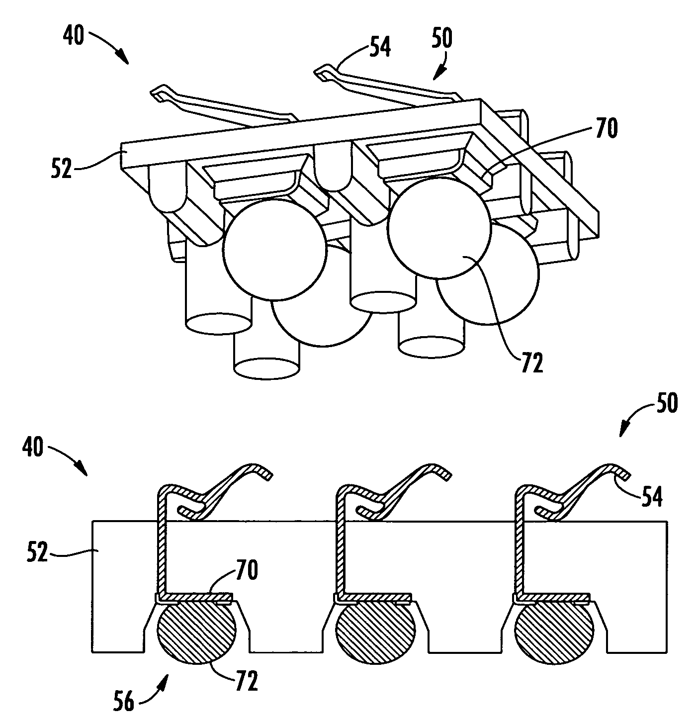
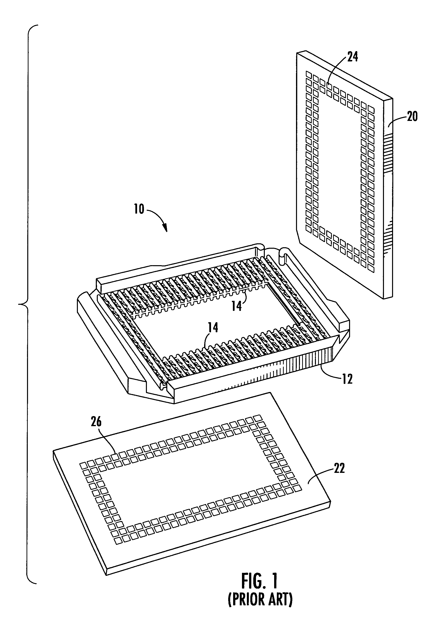
[0017]FIGS. 4–7 depict an interconnect device 40 according to various embodiments of the present invention. The interconnect device 40 may be used to electrically interconnect contacts 42 on a first component 44 to corresponding contacts 46 a second component 48. FIG. 4 is a perspective view of the interconnect device 40 together with the first and second components 44, 48. FIG. 5 is a perspective side view of a portion of the interconnect device 40 with a portion of the second (e.g., bottom) component 48. FIG. 6 is another perspective view of a portion of the interconnect device 40 and FIG. 7 is a top plan view of a portion of the interconnect device 40.

[0018]The contacts 42, 46 may be, for example, lands or pads of various shapes and sizes. For example, as illustrated in FIG. 4, each contact 42, 46 may be a land that is a rectangular shaped flat surface. The plurality of contacts 42, 46 of the first and second components 44, 48, arranged in rows / columns as shown in FIG. 4, may be ...


PUM


Abstract

An interconnect device for electrically interconnecting two components is disclosed. According to various embodiments, the interconnect device includes a frame having a upper side and a lower side, a first plurality of beam contacts on the upper side for connection to contacts of the first component, and a second plurality of contacts on the lower side of the frame for connection to contacts of the second component. The beam contacts on the upper side of the frame are arranged so that the sum of the sideways wipe forces caused by compression of the beam contacts on the upper side due to connection of the first component to the interconnect device approximately equals zero.

Description

BACKGROUND OF INVENTION[0001]The present invention pertains to interconnect devices for electrically interconnecting the contacts of a first component to contacts of a second component.[0002]An electrical interconnector having a plurality of electrical conductors can be used to interconnect one electronic component, such as a microprocessor or ASIC, to another electronic component, such as a printed circuit board. Typically, interconnect devices include a frame having two opposed contact surfaces for respective engagement with a corresponding contact surface of one of the electronic components. Electrical conductors (or contacts) on each side of the frame are electrically connected to the contacts of the respective components such that the two components are thereby electrically connected. The frame of the interconnect device functions to secure the positions of the electrical conductors relative to one another and to electrically isolate the electrical conductors from one another.[...

Claims


Application Information

Patent Timeline
Patent Type & Authority Patents(United States)
IPC IPC(8): H01R11/03H01R12/00H01R13/24
CPCH01R11/03H01R13/2442H01R12/714
Inventor MOWRY, THOMAS E.
Owner TELEDYNE
Learn More