Method and system for evaluating the efficiency of an air conditioning apparatus

a technology of air conditioning apparatus and efficiency evaluation, which is applied in the direction of refrigeration components, digital computer details, special data processing applications, etc., can solve the problems of chiller problems, inefficient operation, and energy cost of air conditioning system type used in high-rise and other commercial buildings, and achieve the effect of computing chiller efficiency

Inactive Publication Date: 2005-12-06
CHILLERGY SYST
View PDF32 Cites 155 Cited by
  • Summary
  • Abstract
  • Description
  • Claims
  • Application Information

AI Technical Summary

Benefits of technology

[0013]As indicated above, the computing device can communicate information that relates to multiple chillers. The chillers can be installed at different geographic locations from one another. A user can select one of these chillers and, for the selected chiller, initiate any suitable operations, including, for example, inputting chiller operating parameters and other data, outputting a log record of collected chiller parameter data, and computing chiller efficiency.

Problems solved by technology

The energy cost of operating an air conditioning system of the type used in high-rise and other commercial buildings can constitute the largest single cost in operating a building.
Yet, unbeknownst to most building managers, such systems often operate inefficiently due to undesirable operating conditions that could be corrected if they were identified.
It has long been known in the art that certain operating parameters are indicative of chiller problems and inefficient operation.
Merely estimating chiller efficiency does not help maintenance personnel to improve efficiency or even recognize the true monetary cost of the inefficiency.
Moreover, even if inefficient operation is recognized from abnormal temperature and pressure readings, there are few guidelines known in the art that maintenance personnel can use to diagnose and correct the cause of the inefficiency.

Method used


Image

  • Method and system for evaluating the efficiency of an air conditioning apparatus
  • Method and system for evaluating the efficiency of an air conditioning apparatus
  • Method and system for evaluating the efficiency of an air conditioning apparatus

Examples


Embodiment Construction

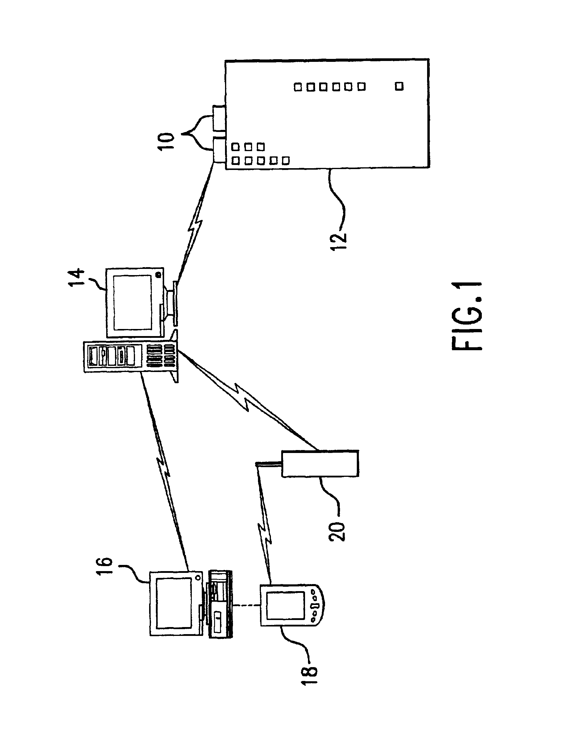
[0042]As illustrated in FIG. 1, two or more chillers 10 are installed on a building 12. As described below, a person responsible for maintaining chillers 10 or other person having an interest in their efficiency can use the system of the present invention to evaluate the efficiency at which they are operating and whether maintenance of any chiller components may improve operating efficiency.

[0043]Each of chillers 10 can communicate data with a server computer 14. A client computer 16, located remotely from server computer 14, can communicate data with server computer 14 via a network such as the Internet or a portion thereof. Also illustrated is a portable or handheld data device 18 that can be docked or synchronized with client computer 16 to communicate data with it or, alternatively or in addition, that can communicate with server computer 14 via a wireless network service 20. Server computer 14 can communicate not only with chillers 10 but also in the same manner with other chil...


PUM


Abstract

Air conditioning chiller operating efficiency is evaluated in response to chiller operating parameters input to a computing device which calculates separately the efficiencies of the condenser and evaporator components of the chiller. Additional efficiency calculations are performed to identify specific causes of inefficiency in the condenser and evaporator. The computing device also adjusts the efficiency calculations as appropriate to account for actual compressor current load conditions. The device determines whether chiller efficiency is being compromised by poor performance of one or more chiller components, calculates inefficiency values, estimates the cost of the inefficiency, identifies specific causes of the inefficiency, and suggests appropriate remedial actions to restore maximum efficiency of the chiller.

Description

CROSS-REFERENCE TO RELATED APPLICATION[0001]The benefit of U.S. provisional patent application Ser. No. 60 / 291,248, filed May 15, 2001, entitled METHOD AND SYSTEM FOR EVALUATING THE EFFICIENCY OF AN AIR CONDITIONING APPARATUS,” is hereby claimed under 35 U.S.C. § 119, and the specification thereof is incorporated herein in its entirety by this reference.BACKGROUND OF THE INVENTION[0002]1. Field of the Invention[0003]The present invention relates generally to air conditioning system monitoring and, more specifically, to monitoring and evaluating the performance and efficiency of chiller units.[0004]2. Description of the Related Art[0005]The energy cost of operating an air conditioning system of the type used in high-rise and other commercial buildings can constitute the largest single cost in operating a building. Yet, unbeknownst to most building managers, such systems often operate inefficiently due to undesirable operating conditions that could be corrected if they were identified...

Claims


Application Information

Patent Timeline
Patent Type & Authority Patents(United States)
IPC IPC(8): F24F11/00G05B23/02
CPCF24F11/0086F24F2011/0094F24F11/30F24F11/47
Inventor SEIGEL, LAWRENCE J.
Owner CHILLERGY SYST
Why Eureka
Try Eureka