Filament trimmer with dual triggers

a trimmer and trigger technology, applied in the field offilament trimmer, can solve the problems of operator switching between the two available modes of operation, difficulty in intuitively understanding the pivoting of the handle, and difficulty in initially figuring out how to reposition the upper handle to use the trimmer in both the trim and edge modes of operation

Inactive Publication Date: 2005-12-13
TORO CO THE
View PDF2 Cites 19 Cited by
  • Summary
  • Abstract
  • Description
  • Claims
  • Application Information

AI Technical Summary

Benefits of technology

[0005]This invention relates to a filament trimmer having dual triggers on the handle with one trigger being used in the trim mode and one trigger in the edge mode. This allows use of the trimmer in both modes without requiring a handle that must be repositioned relative to the rest of the trimmer to operate in both modes.

Problems solved by technology

However, some operators do not intuitively understand how to pivot the handle and thus find it difficult to initially figure out how to reposition the upper handle to use the trimmer in both the trim and edge modes of operation.
In addition, the need to stop the trimmer and manually reposition the upper handle is inconvenient and thus discourages some operators from switching between the two available modes of operation.

Method used


Image

  • Filament trimmer with dual triggers
  • Filament trimmer with dual triggers
  • Filament trimmer with dual triggers

Examples


first embodiment

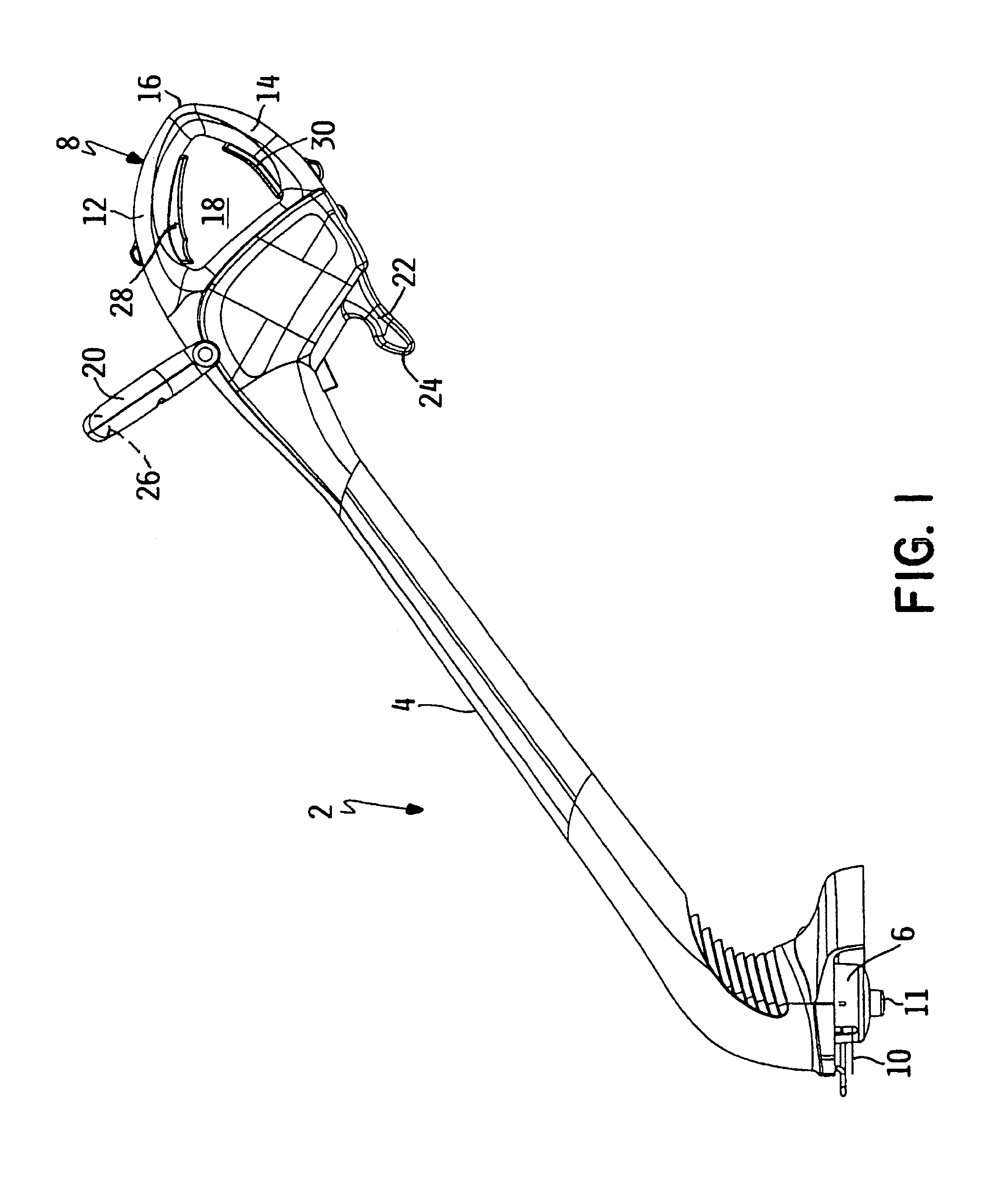
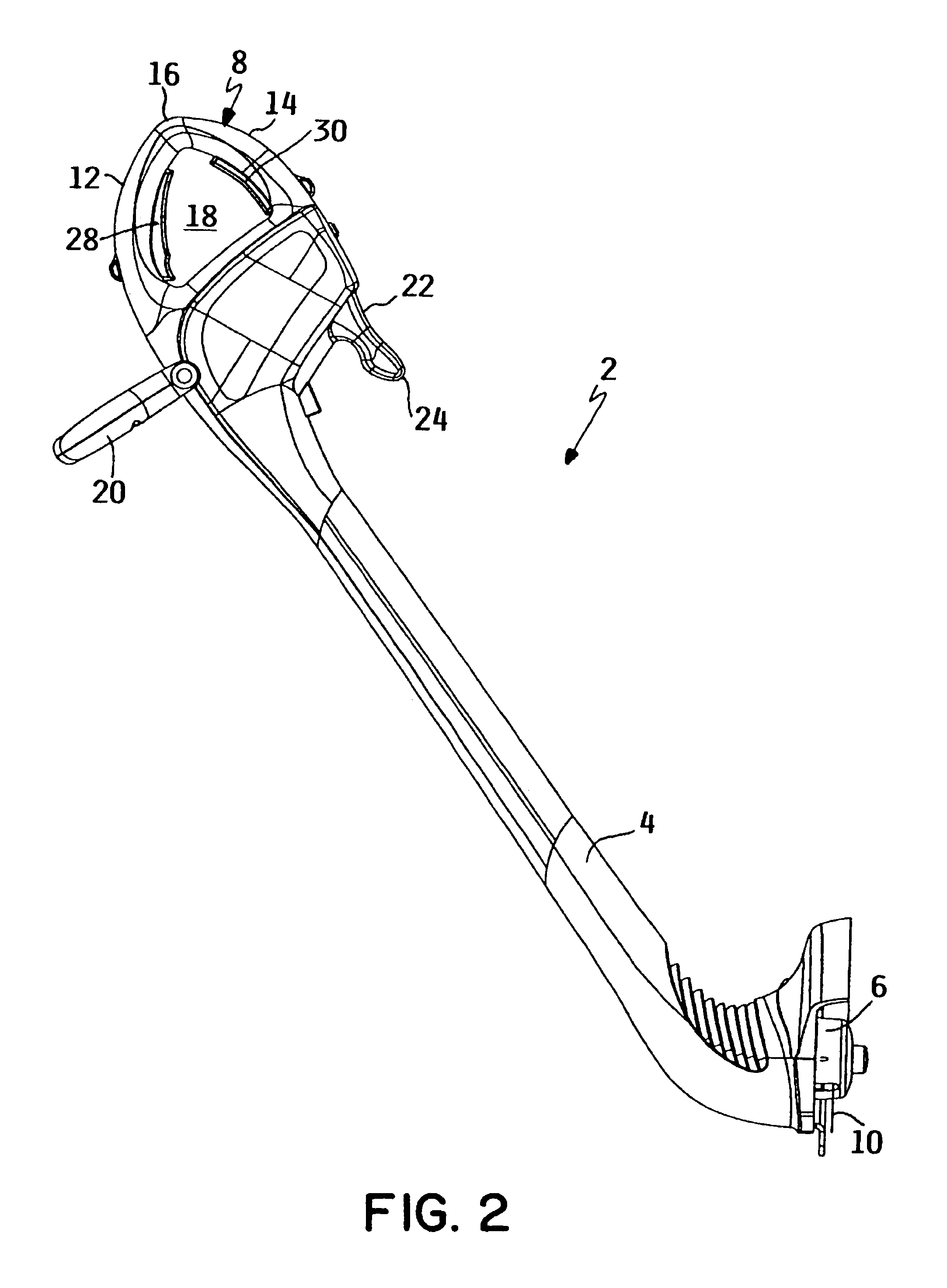
[0020]a filament trimmer 2 according to this invention is illustrated in FIGS. 1-4.

[0021]Trimmer 2 includes a housing 4 carrying a rotatable trimmer head 6 at the lower end of housing 4. Housing 4 includes a handle 8 at the upper end of housing 4 to allow the operator to grip and hold trimmer 2. A drive comprising an electric drive motor (not shown) is provided in housing 4 for rotating trimmer head 6. A rechargeable battery (not shown) is located in housing 4 and is electrically coupled to the motor for powering the motor. When the motor is powered and trimmer head 6 is rotated, a flexible filament 10 extending outwardly from trimmer head 6 is spun in a cutting plane to sever grass or other ground growing vegetation.

[0022]Trimmer head 6 preferably includes a filament feed system that replenishes the flexible filament when filament 10 is shortened due to use. Trimmer head 6 comprises a ground bump head having a ground bump button 11. This allows the operator to selectively actuate t...

second embodiment

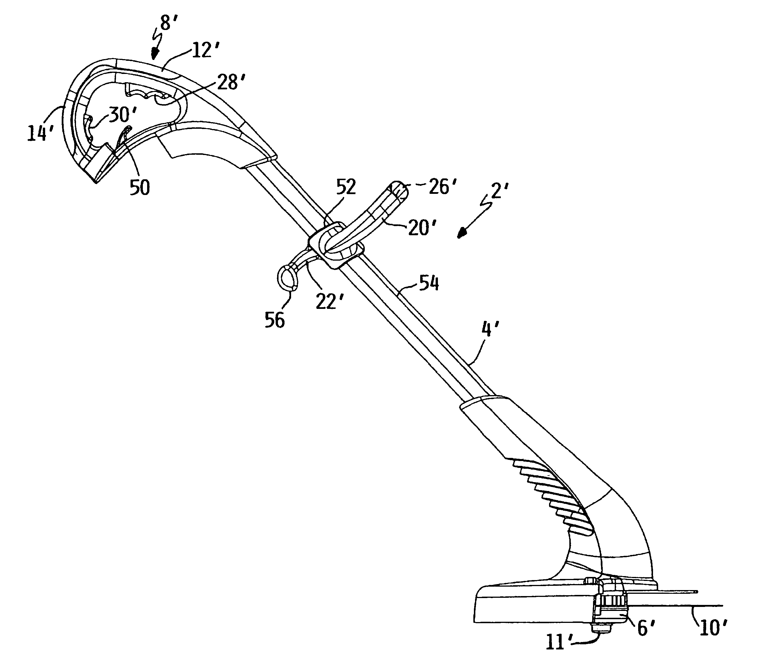
[0035]A second embodiment of a filament trimmer 2′ according to this invention is illustrated in FIGS. 5-12. Since trimmer 2′ has many common features to that of the first embodiment, the same reference numerals applied to components of trimmer 2 of the first embodiment will be used to refer to the corresponding components of trimmer 2′ of the second embodiment except that such identical reference numerals used in conjunction with trimmer 2′ of the second embodiment will carry a prime suffix, e.g. trimmer 2′ instead of trimmer 2. Only the major points of difference between trimmers 2 and 2′ will be specifically described hereafter, the structure and operation of the two trimmers 2 and 2′ otherwise being identical for which a separate description would be redundant and unnecessary.

[0036]Trimmer 2′ of the second embodiment is not battery operated, but instead carries an electrical socket (not shown) into which one end of an electrical extension cord (not shown) could be plugged. An en...


PUM


Abstract

A filament trimmer includes a rotatable trimmer head having an outwardly extending filament. The trimmer has an upper handle that the operator can grip to operate the trimmer in either a trim mode or an edge mode. In the trim mode, the filament extending outwardly from the trimmer head is positioned in a generally horizontal cutting plane, while in the edge mode the trimmer is reoriented such that the filament is positioned in a generally vertical cutting plane. The upper handle of the trimmer includes dual triggers for selectively starting and stopping rotation of the trimmer head. One trigger is actuated when the trimmer is operated in the trim mode and the other trigger is actuated when the trimmer is operated in the edge mode.

Description

TECHNICAL FIELD[0001]This invention relates to a filament trimmer having an outwardly extending filament that cuts grass or other ground growing vegetation when the filament is rotated in a cutting plane. More particularly, this invention relates to a filament trimmer that is operable in both a trim mode in which the filament rotates in a generally horizontal cutting plane and in an edge mode in which the filament rotates in a generally vertical cutting plane.BACKGROUND OF THE INVENTION[0002]Filament trimmers are well known lawn and garden implements. Such a trimmer includes a rotatable trimmer head that has an outwardly extending flexible filament. When the trimmer head is rotated by a drive contained on the trimmer, the filament is spun in a cutting plane to be able to sever grass or other ground growing vegetation. The drive for rotating the trimmer head may be an electrical motor operated by an electrical power source, e.g. a battery on the trimmer or an electric power cord. The...

Claims


Application Information

Patent Timeline
Patent Type & Authority Patents(United States)
IPC IPC(8): A01D34/84A01D34/90
CPCA01D34/84A01D34/90
Inventor ELLSON, BART T.HURST, JOHN O.SHAFFER, CHADWICK A.
Owner TORO CO THE
Why Eureka
Try Eureka