One-way bidirectional clutch

a one-way, bi-directional, clutch technology, applied in the direction of automatic initiation, gearing details, brake systems, etc., can solve the problems of short field life of locking wedge-type clutches, undesirable chatter or ratcheting, and inability to accommodate relatively large loads and/or shock loads

Active Publication Date: 2005-12-13
CARLYLE JOHNSON MACHINE COMPANY LLC THE
View PDF8 Cites 24 Cited by
  • Summary
  • Abstract
  • Description
  • Claims
  • Application Information

AI Technical Summary

Problems solved by technology

For example, the wrap spring-type is unable to accommodate relatively large loads and / or shock loading.
However, the sprags of the sprag-type clutch are often forced back and forth between to an unlocked and locked position when the operator attempts to drive the input shaft in the same directions as the load on the output shaft.
Such action often results in undesirable chatter or ratcheting.
Because only two points of contact are used to prevent torque from translating torque from the output shaft to the input shaft, the locking wedge-type clutch suffers from a short field life due to failures.

Method used


Image

  • One-way bidirectional clutch
  • One-way bidirectional clutch
  • One-way bidirectional clutch

Examples


Embodiment Construction

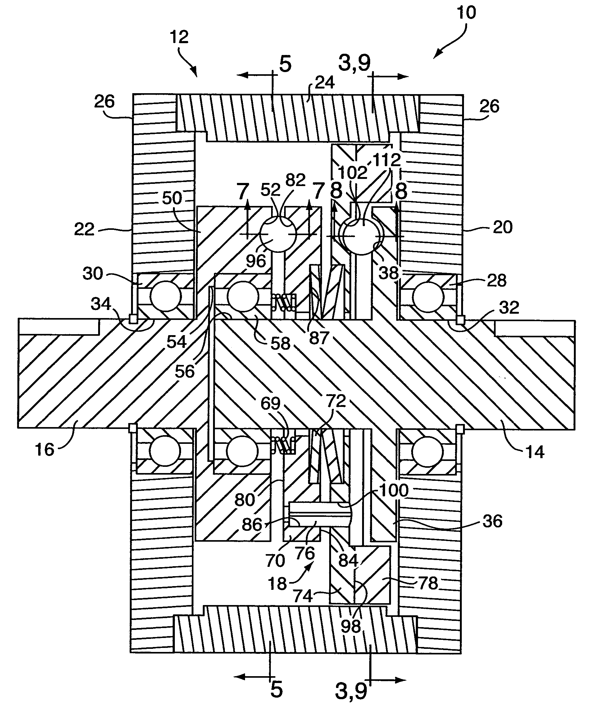
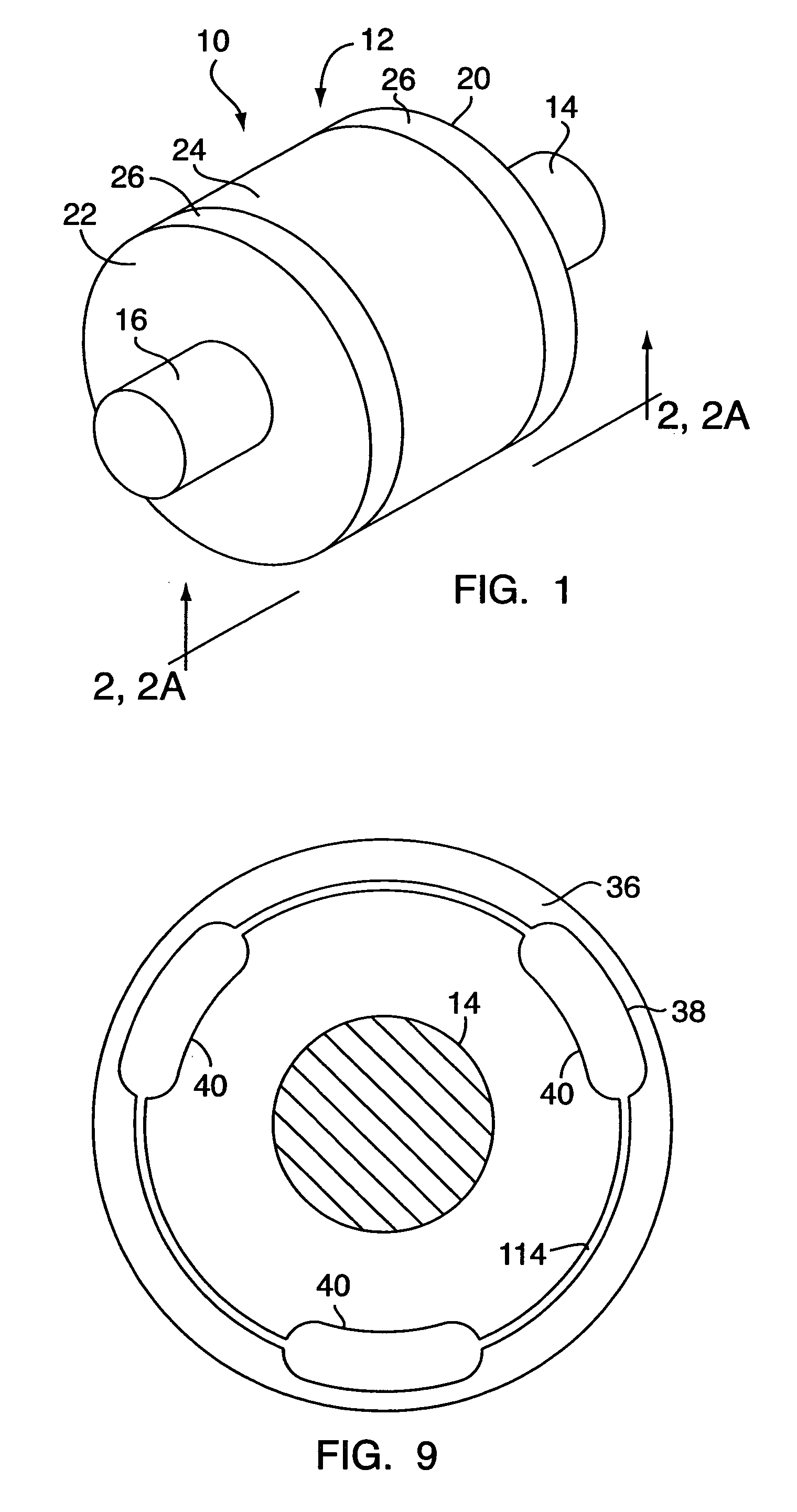
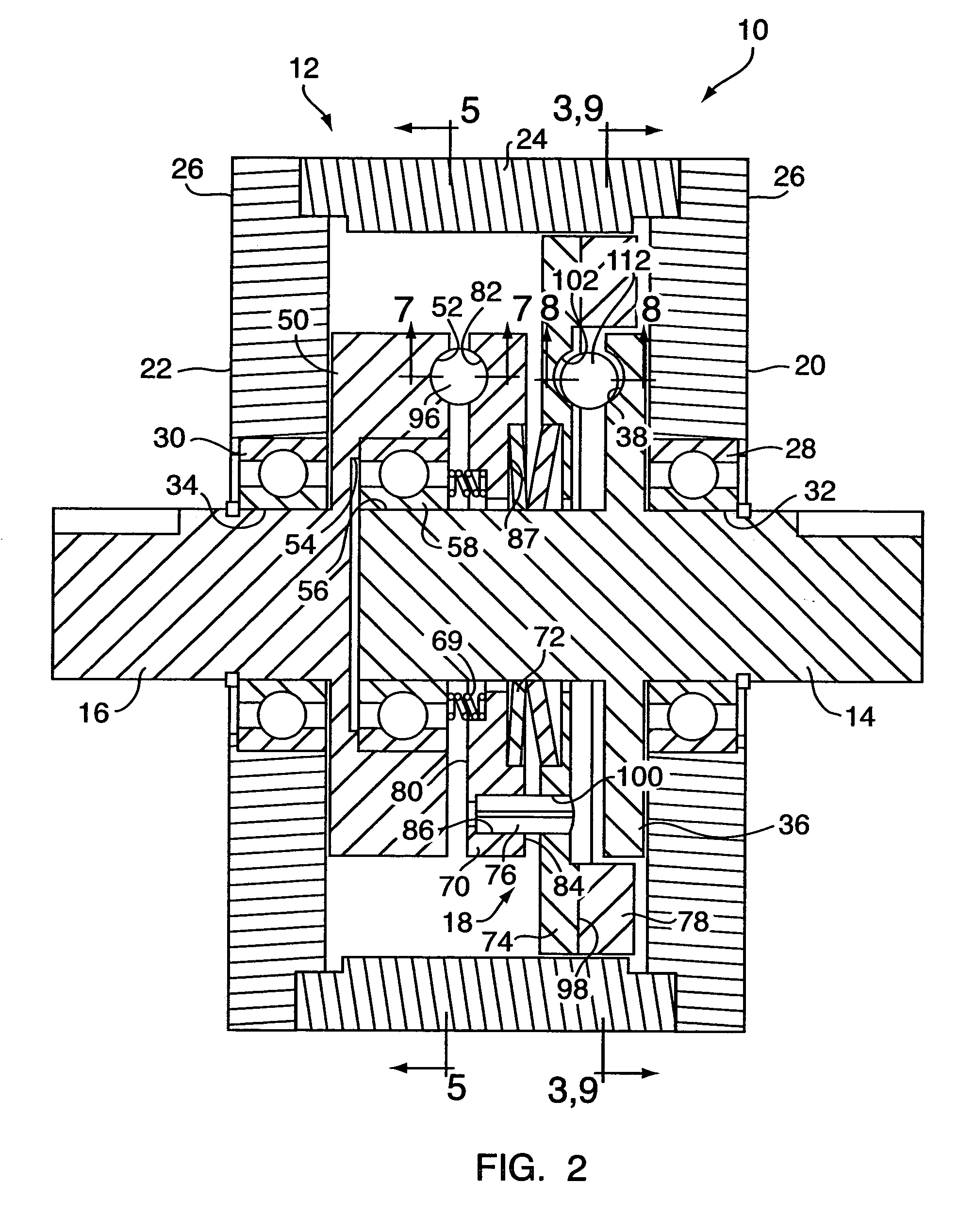
[0025]Referring to FIGS. 1, 2 and 2A, the one-way, bi-directional clutch of the present invention is generally referred to by the numeral 10. The one-way, bi-directional clutch (hereinafter referred to as “the OWBD clutch 10”) includes an outer casing 12, an input shaft 14, an output shaft 16, and a brake assembly 18.

[0026]The outer casing 12 includes a first end 20 and a second end 22 and may have any suitable cross-sectional shape. However, an outer casing 12 with a generally circular cross-sectional shape, as shown in FIG. 1, has particular utility. The outer casing 12 is operable to house and / or support the various components of the OWBD clutch 10. In some embodiments, the outer casing 12 includes a tubular housing 24 with cover caps 26 substantially covering both ends, as shown for example in FIG. 1. However, the present invention is not to be considered so limited. For example, the outer casing 12 may alternatively consist of a first “cup”-shaped portion having a single open e...


PUM


Abstract

According to the present invention, a one-way, bi-directional clutch, includes an outer casing, an input shaft, an output shaft and a brake assembly. The input shaft includes a release cam portion and the output shaft includes a locking cam portion. The brake assembly includes a release cam portion that is complementary to the release cam portion of the input shaft, a locking cam portion that is complementary to the locking cam portion of the output shaft, a biasing element and at least one brake pad. The complementary release cam portion of the input shaft and brake assembly are operable to move the brake assembly to a release position when the sufficient torque is applied to the input shaft. The complementary locking cam portions of the output shaft and the brake assembly are operable to move the one or more brake pads to the brake position when the sufficient torque applied to the output shaft.

Description

BACKGROUND OF THE INVENTION[0001]1. Field of the Invention[0002]The present invention relates to mechanical clutches, in general and, more particularly, to one-way, bi-directional clutches.[0003]2. Background Information[0004]One-way, bi-directional clutch devices are mechanical devices that transmit torque from an input shaft to an output shaft in either rotational direction, but do not transmit torque from the output shaft to the input shaft. One-way, bi-directional clutches typically include a brake assembly that engages when more torque is applied to the output shaft than the amount of torque applied to the input shaft. The brake assembly, when engaged, prevents torque from translating from the output shaft to the input shaft in both directions.[0005]One-way, bi-directional clutches, also commonly known as “no-back clutches,” are used in numerous applications. No-back clutches are utilized where a user desires 1) to selectively control the movement of a mechanical device using a...

Claims


Application Information

Patent Timeline
Patent Type & Authority Patents(United States)
IPC IPC(8): F16D59/00F16D67/00F16D67/02
CPCF16D67/02F16D2125/38
Inventor GAMACHE, MICHAEL E.
Owner CARLYLE JOHNSON MACHINE COMPANY LLC THE
Why Eureka
Try Eureka