
Elevator system having terminals with wireless transmitting/receiving unit

a technology of elevator system and terminal, which is applied can solve the problems of not being able to reduce the number of elevator wires in the building serviced by the elevator system, and the above-mentioned conventional technology in the field of elevator system has not been widely used, and achieves the effect of narrow communication rang

Inactive Publication Date: 2005-12-20
HITACHI LTD
View PDF24 Cites 5 Cited by
  • Summary
  • Abstract
  • Description
  • Claims
  • Application Information

AI Technical Summary

Benefits of technology

[0007]An object of the present invention is to provide an elevator system in which information can with certainty be transmitted between an elevator control unit and a car, a counterweight or a landing entrance on each floor, even if wireless transmitting / receiving units having a comparatively narrow communicable range are employed.
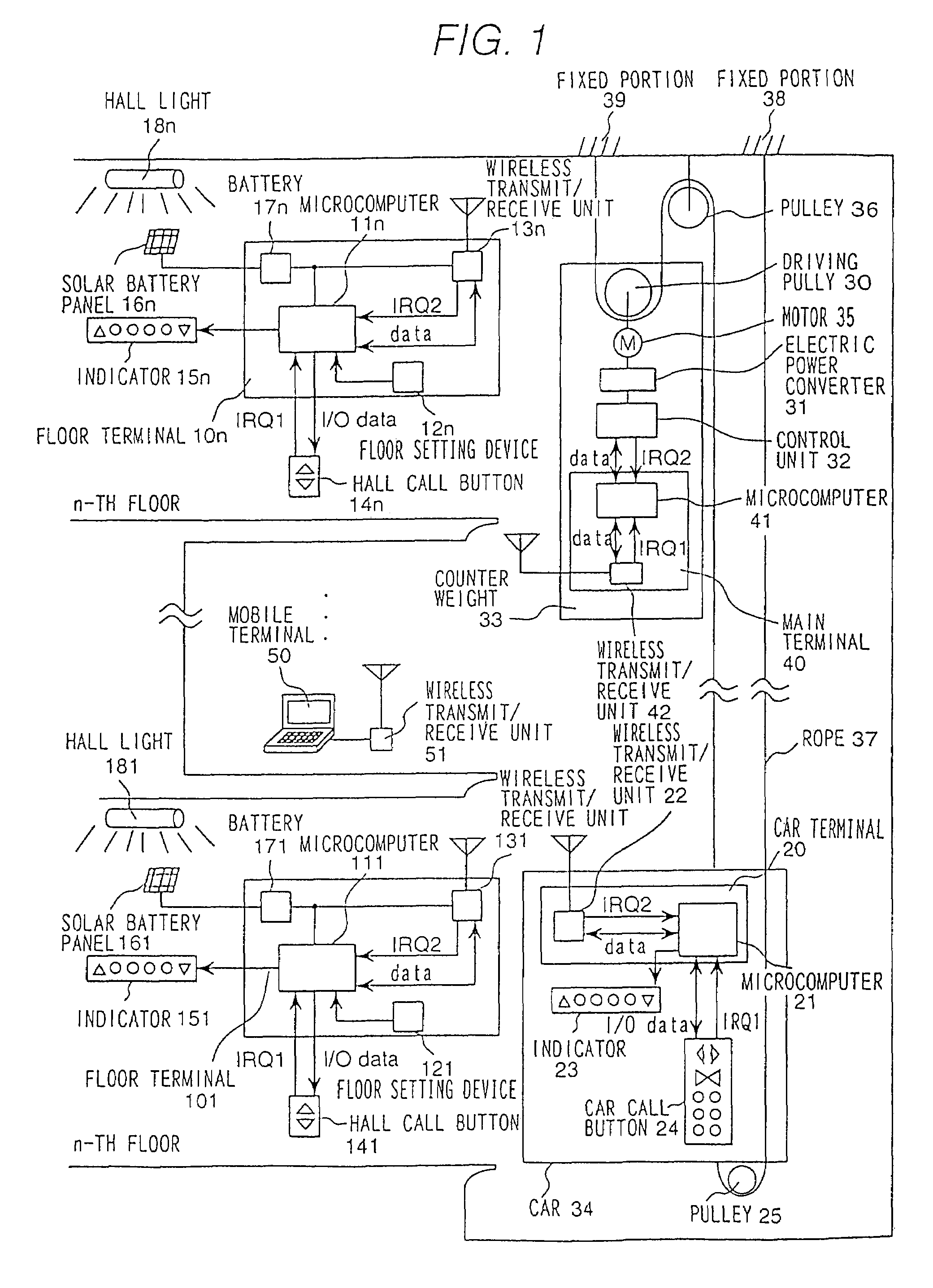
[0009]By the use of wireless transmission in which information is relayed using a terminal within a communicable range, it is possible to communicate between a sending side and a receiving side which are too far apart to directly communicate from one to the other, and in this way, it is possible to carry out the sending and receiving of information in an elevator system using wireless transmitting / receiving units having a relatively narrow communication range.

Problems solved by technology

The above-mentioned conventional technologies in the field of elevator system have not been widely used because it has been presumed that a wireless unit having a large output capacity needs to be used corresponding to the height of the building.
Further, none of the known technologies is sufficient to reduce the number of elevator wires in the building serviced by the elevator system.

Method used


Image

  • Elevator system having terminals with wireless transmitting/receiving unit
  • Elevator system having terminals with wireless transmitting/receiving unit
  • Elevator system having terminals with wireless transmitting/receiving unit

Examples


Embodiment Construction

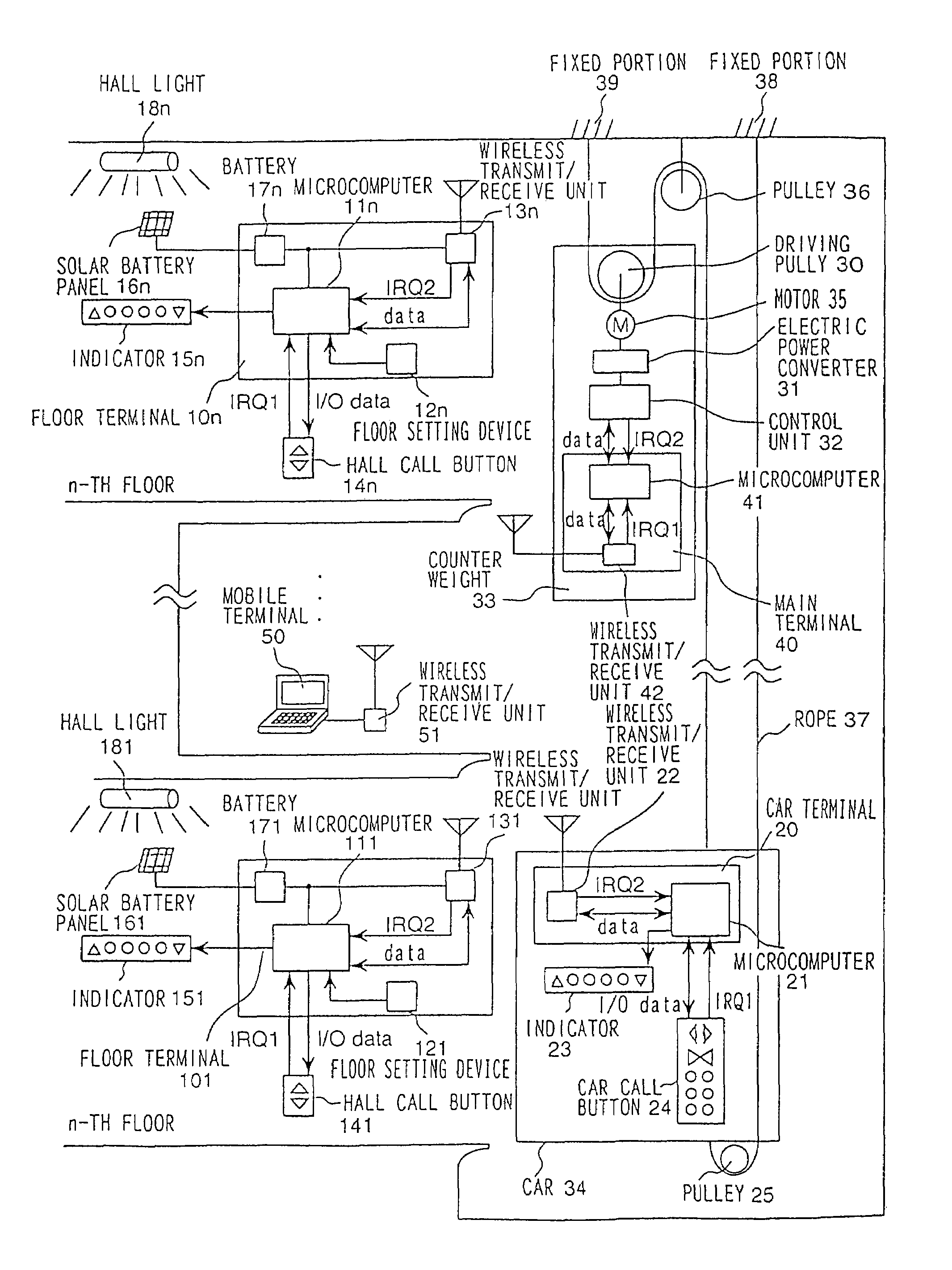
[0021]FIG. 1 is a block diagram showing the construction of an embodiment of an elevator system in accordance with the present invention. A rope 37 is wound around a pulley 36 suspended from a ceiling of an elevator hoistway, and an elevator car 34 and a counterweight 33 are suspended on the rope on either side of the pulley 36 so as to counter each other in weight. That is, one end of the rope 26 is fixed to a portion 38 in the ceiling, and the rope goes downward from there and passes though a pulley 25 mounted on the lower side of the car 34, turns upward, and then is wound around the pulley 36. Further, the rope 37 goes downward from the pulley 36 and passes through a drive pulley 30, from which the counterweight 33 is suspended, and is turned upward from the pulley 30, with the other end thereof being fixed to a position 39 in the ceiling.

[0022]The elevator is driven by a rotation force of a motor 35, which is mounted on the counterweight 33. That is, an electric power converter...


PUM


Abstract

An elevator system in which a car travels upward and downward among a plurality of floors. The elevator system includes terminals each having a wireless transmitting / receiving unit. One of the terminals is correspondingly provided for at least one of the plurality of floors and another of the terminals is correspondingly provided for the car and at least one of a counterweight. A mobile terminal is provided which enables wireless transmitting / receiving of signals between the terminals which are arranged within a predetermined distance of each other.

Description

CROSS REFERENCE TO RELATED APPLICATIONS[0001]This application is a continuation application of Ser. No. 10 / 201,962, filed Jul. 25, 2002, now U.S. Pat. No. 6,598,710, which is a continuation application of Ser. No. 09 / 721,678, filed Nov. 27, 2000, now U.S. Pat. No. 6,446,761, the subject matter of which is hereby incorporated by reference herein.BACKGROUND OF THE INVENTION[0002]The present invention relates to an elevator system in which information is transmitted and received by wireless transmission between an elevator control unit and terminals in an elevator car and on each of the floors serviced by the elevator system.[0003]An elevator is operated in response to requests generated through operation of a hall call button placed at a landing entrance on each of the floors and a car call button (also called a destination button) located inside the elevator car, and the statuses of the hall call button on each of the floors and the car call button in the car are sequentially transmi...

Claims


Application Information

Patent Timeline
Patent Type & Authority Patents(United States)
IPC IPC(8): B66B3/00B66B1/00B66B1/34
CPCB66B1/34B66B1/3415B66B3/00B66B1/00
Inventor MOTOYAMA, NOBUHISAINABA, HIROMIKAWABATA, ATSUSHIOHKURA, YOSHINORIYAMASHITA, KENICHI
Owner HITACHI LTD
Learn More