Plant for friction stir welding

a technology of stir welding and plant, which is applied in the direction of soldering apparatus, manufacturing tools, auxillary welding devices, etc., can solve the problems of limited use, joint production having internal cavities, and welding technique not being used to join together workpieces

Inactive Publication Date: 2001-10-09
ESAB AB
View PDF2 Cites 31 Cited by
  • Summary
  • Abstract
  • Description
  • Claims
  • Application Information

AI Technical Summary

Problems solved by technology

Because the dimensions of the profile sections produced today by the extruding technique are comparatively small and because the welding methods used at present for joining together aluminium profile sections fail to provide a wholly satisfactory result with respect to strength, finish, and deformation, aluminium has not gained but restricted use, despite the above-mentioned advantages that this material possesses.
One problem encountered when using the welding technique according to the above patent publications to join together aluminium profile sections is that this welding technique can only be used to join together workpieces separated by a very narrow air gap.
Should the air gap exceed this critical value, which among other things depends on the thickness of the sheet metal from which the profile sections are made, a joint is produced having internal cavities and impaired strength.
In consequence thereof, extruded aluminium profile sections that cannot be produced to exactly precise dimensions by existing manufacturing methods, require some pre-treatment to avoid too large gaps between the profile sections.
This is particularly important in the case of the welding together of elongate profile sections, in which even small deformations may give rise to unacceptable deviations.
Another problem encountered in friction stir welding is that deformations of the profile sections may occur also during the welding operation proper, as the sections are exposed to the effects of heat.
However, this deformation is of lesser magnitude than in the case of MIG and TIG welding, since the temperature never reaches the melting point.
However, the result may be that the dimensions of the end product fail to be within the acceptable tolerance range, despite the pre-treatment of the profile section.
This problem is encountered also in applications wherein the tolerance range of the end product is narrower than that of the participating workpieces.

Method used


Image

  • Plant for friction stir welding
  • Plant for friction stir welding
  • Plant for friction stir welding

Examples


Embodiment Construction

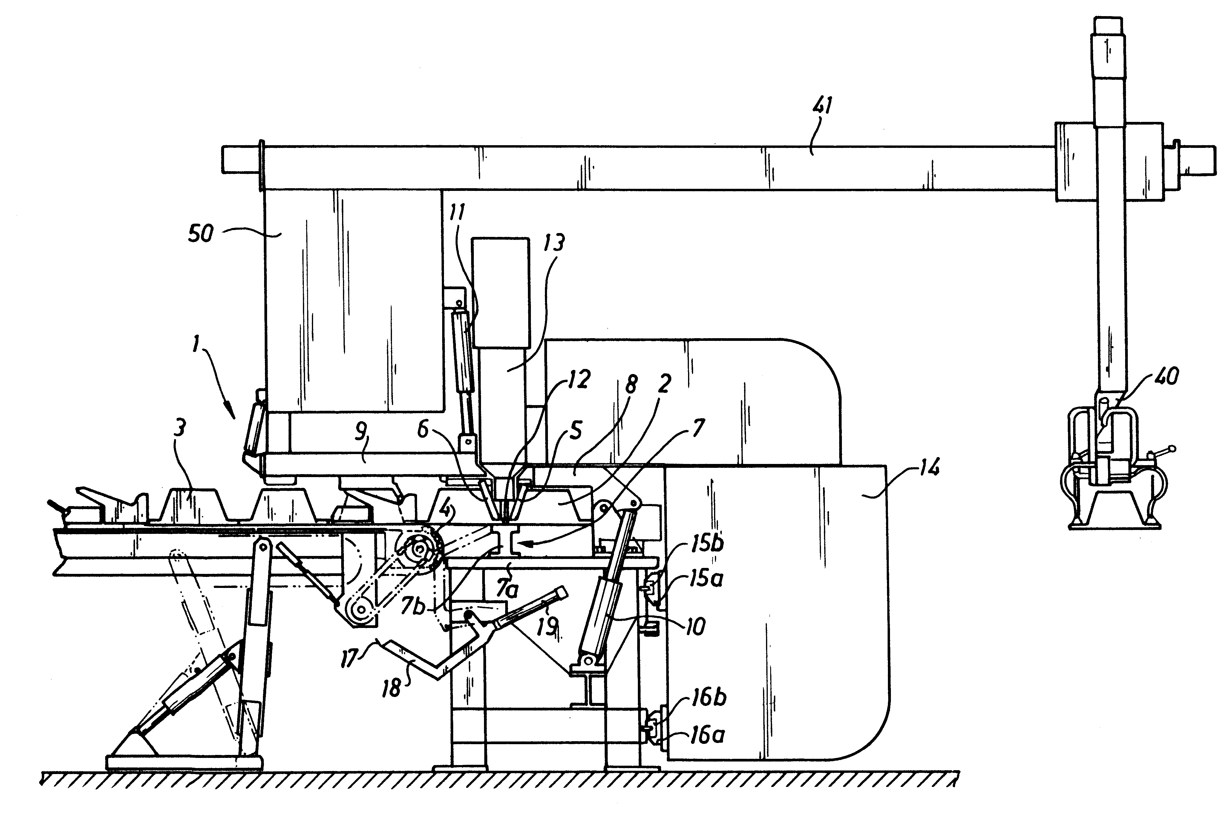
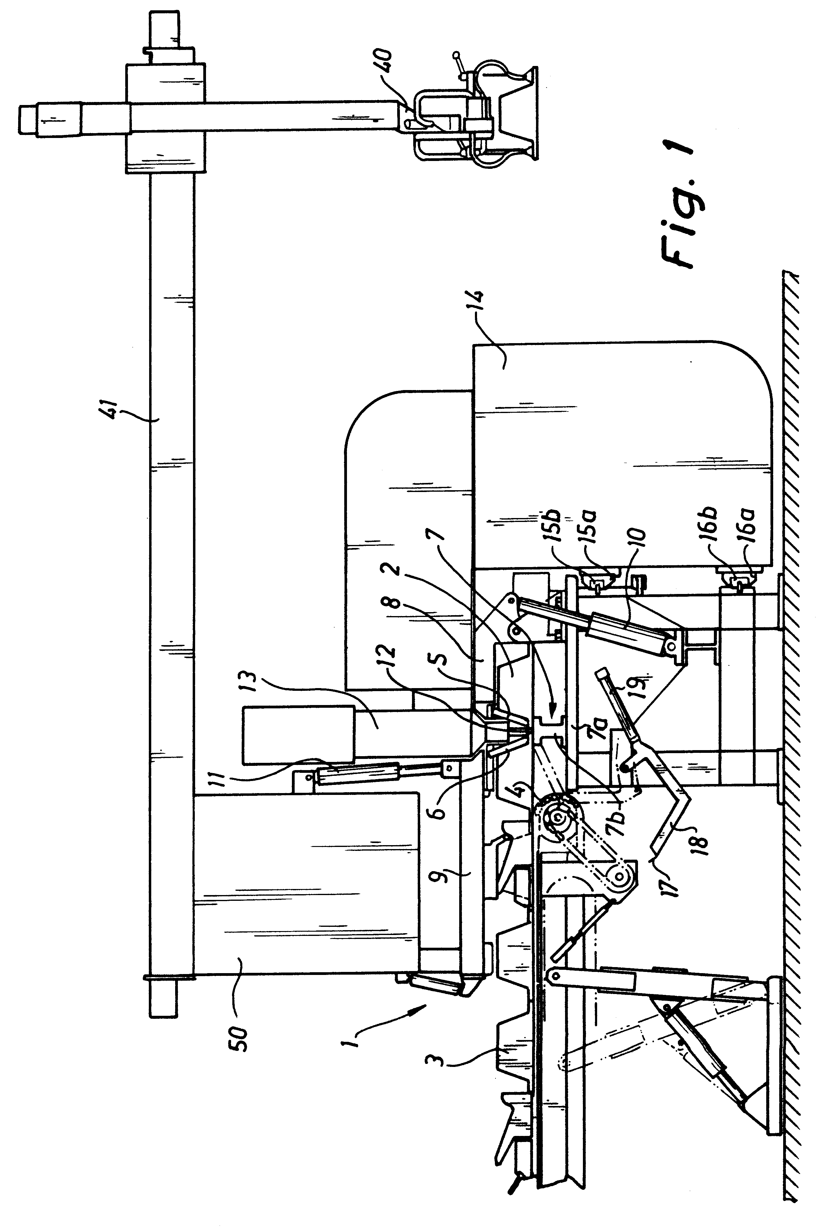
The plant 1 illustrated in FIG. 1 is adapted to be used to weld together extruded aluminium profile sections 2 in order to form an aluminium panel 3. The expression aluminium is used herein to designate either pure aluminium or an alloy of aluminium and another metal, such as mangnesium. The number of aluminium profile sections to be welded together is determined by the width of the profile section in question, which could for example have a width of 300 mm and a length of 12 m, and by the requested width of the finished panel. The manufacture is effected by welding a fresh aluminium profile section to the right-hand marginal edge of the immediately preceding profile section, as illustrated in FIG. 1, this immediately preceding profile section in turn having previously been welded to the right-hand marginal edge of the preceding profile section. In other words, the width of the aluminium profile section being manufactured increases by the width of one profile section in each separat...


PUM

PropertyMeasurementUnit
lengthaaaaaaaaaa
widthaaaaaaaaaa
lengthaaaaaaaaaa

Abstract

A plant for friction stir welding, comprising a welding probe, a drive unit driving the welding probe, a work table supporting the workpiece or workpieces to be welded, and at least one clamping means for clamping the workpieces to one another or to the work table, or the workpieces to the work table, respectively, during the welding operation. The plant likewise comprises a milling tool.

Description

The present invention relates to a plant for friction stir welding, comprising a welding probe, a drive unit driving the welding probe, a work table supporting the workpiece or workpieces to be welded, and at least one clamping means for clamping the workpieces to one another and / or to the work table or the workpiece to the work table, respectively, during the welding operation.DESCRIPTION OF THE RELATED ARTThe definition friction stir welding designates a welding method according to which the workpieces to be joined together are plasticized along their joint line by supply of frictional heat from a rotating welding probe which is caused to move along the joint between the workpieces while at the same time being pressed against the workpieces. As described in WO93 / 10935 and WO95 / 26254 the welding probe should be manufactured from material harder than the workpieces, and during the welding operation the workpieces should be securely fixed relative to one another and to the work table...

Claims


Application Information

Patent Timeline
Patent Type & Authority Patents(United States)
IPC IPC(8): B23K20/12
CPCB23K20/122B23K20/126
Inventor LARSSON, ROLF
Owner ESAB AB
Why Eureka
Try Eureka