Method and system for power management control in passive optical networks

a technology of optical network and power management control, applied in the field of passive optical network, can solve problems such as complex hardware, and achieve the effects of narrowing the dynamic range, reducing manufacturing costs, and simple and cheaper optical components

Inactive Publication Date: 2008-03-06
AVAGO TECH INT SALES PTE LTD
View PDF40 Cites 33 Cited by
  • Summary
  • Abstract
  • Description
  • Claims
  • Application Information

AI Technical Summary

Benefits of technology

[0013]The present invention provides a system and method for power management control performed and implemented by optical line terminals (OLTs). Specifically, the disclosed system in the OLT acquires the received optical power of each optical network unit (ONU) in a passive optical network (PON). The OLT sets the reception threshold of its optical receiver with the acquired reception level for an ONU prior to receiving

Problems solved by technology

However, on the other hand, such a solution requires complicated h

Method used


Image

  • Method and system for power management control in passive optical networks
  • Method and system for power management control in passive optical networks
  • Method and system for power management control in passive optical networks

Examples


Embodiment Construction

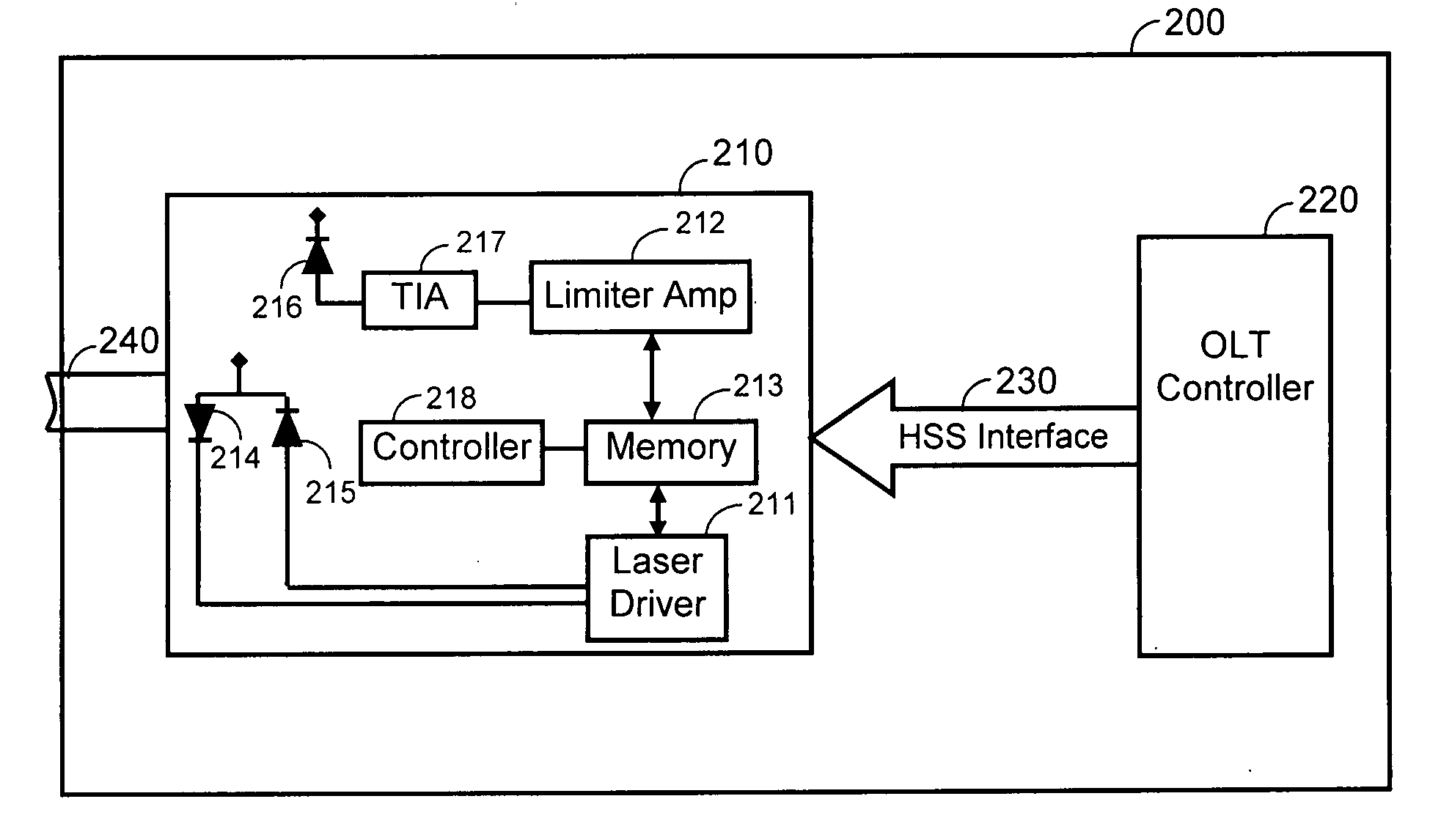
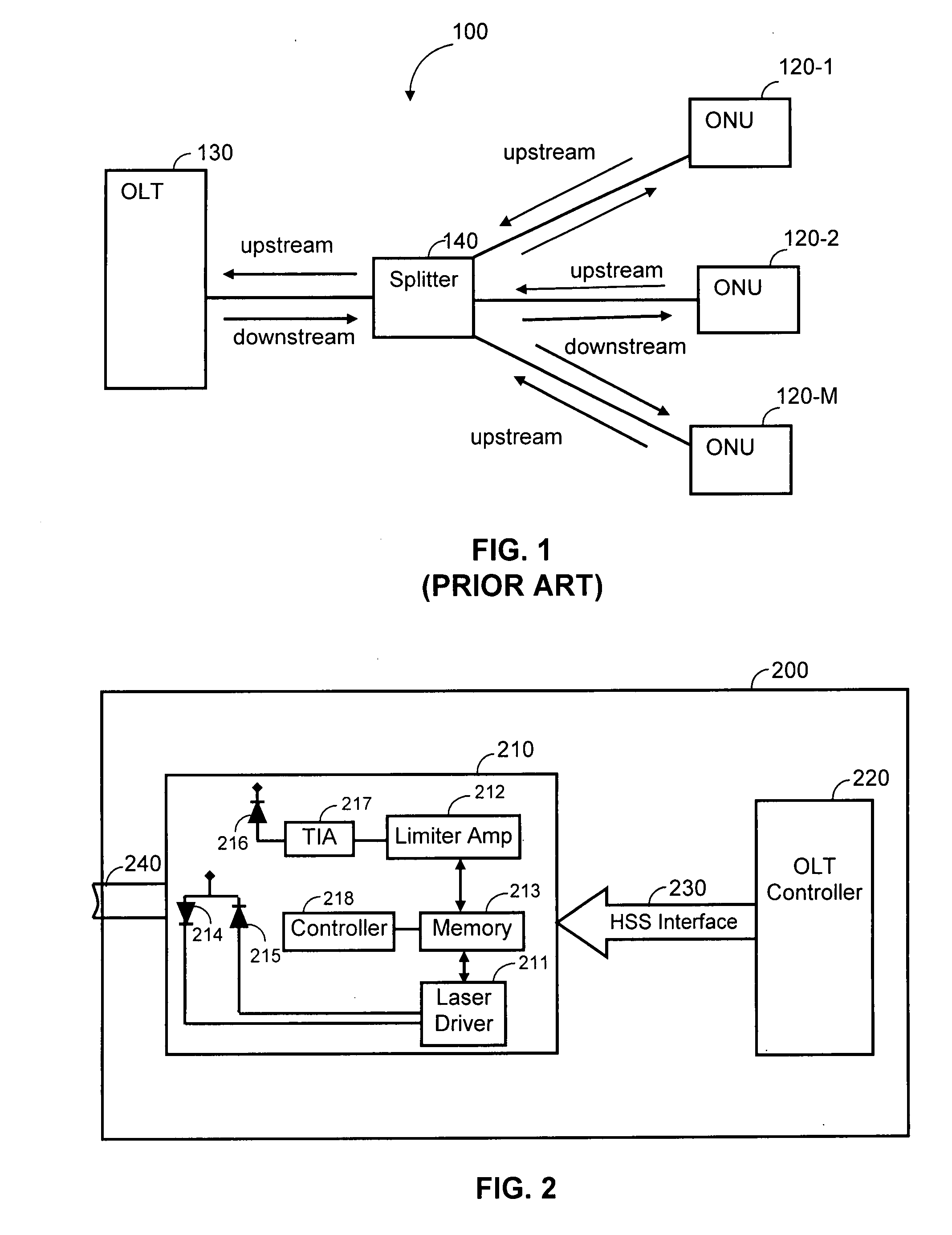
[0029]FIG. 2 shows a schematic block diagram of an OLT 200 that includes a physical (PHY) layer interface 210 and an OLT controller 220 communicating using high speed serial (HSS) interface 230. Other circuitry and components of a typical OLT system are not shown, merely for keeping the description simple and without limiting the scope of the disclosed invention. It should be noted that the HSS interface 230 can be replaced with other types of interface that would allow to the PHY layer interface 210 and OLT controller 220 to communicate with each other.

[0030]The PHY layer interface 210 includes an optical transceiver that acts to transmit and receive optical signals to and from the ONUs via an optical fiber 240. Specifically, the PHY layer interface 210 comprises of a laser driver 211, a limiter amplifier 212, a memory 213, a laser diode 214 coupled to a photodiode 215, a photodiode 216 coupled to a transimpedance amplifier (TIA) 217, and a PHY controller 218.

[0031]The laser driver...


PUM


Abstract

An optical line terminal (OLT) performs power management control in a passive optical network (PON) by acquiring a respective reception level for each optical network unit (ONU) in the PON and maintaining a reception table that stores the respective reception level for each ONU. Prior to receiving a burst signal from an ONU, it sets a reception threshold of an optical receiver at the OLT with the reception level of the ONU.

Description

CROSS-REFERENCE TO RELATED APPLICATION[0001]This application claims priority from U.S. provisional patent No. 60 / 840,955 filed on Aug. 30, 2006, whose contents are wholly incorporated herein by reference.REFERENCES SITEDPatents[0002]U.S. Pat. No. 6,801,497October 2004Van DriesscheU.S. Pat. No. 6,498,667December 2002Masucci, et al.U.S. Pat. No. 20040247316December 2004Soto; et al.Other References[0003]GPON Standard Chapter IVTECHNICAL FIELD[0004]The present invention relates generally to passive optical networks (PONs), and more particularly to power management control in such networks.BACKGROUND OF THE INVENTION[0005]A passive optical network (PON) comprises an optical line terminal (OLT) connected to multiple optical network units (ONUs) in a point-to-multi-point network. New standards have been developed to define different types of PONs, each of which serves a different purpose. For example, the various PON types known in the related art include a Broadband PON (BPON), an Etherne...

Claims


Application Information

Patent Timeline
IPC IPC(8): H04J14/08
CPCH04B10/27H04J3/0682H04Q2011/0049H04Q11/0067H04J3/1694
Inventor SITTON, GALHAREL, JACOBNAAMAN, IFAT
Owner AVAGO TECH INT SALES PTE LTD
Why Eureka
Try Eureka