Image processing apparatus for generating a wide dynamic range image

a technology of image processing and dynamic range, applied in the field of image processing apparatus, can solve the problems of affecting the image quality of the person, flat or dull image, etc., and achieve the effect of narrow density rang

Inactive Publication Date: 2008-12-02
OLYMPUS CORP
View PDF9 Cites 30 Cited by
  • Summary
  • Abstract
  • Description
  • Claims
  • Application Information

AI Technical Summary

Benefits of technology

[0016]It is an object of the present invention to provide an image processing apparatus in which contrast can be maintained throughout the entire luminance range of the image, even if the dynamic range is compressed to permit a display system having a narrow density range.

Problems solved by technology

With the conventional compression technique, the contrast of the person will be degraded and a flat or dull image will result.
The result may be an image having wide dynamic range but low image quality.

Method used


Image

  • Image processing apparatus for generating a wide dynamic range image
  • Image processing apparatus for generating a wide dynamic range image
  • Image processing apparatus for generating a wide dynamic range image

Examples


first embodiment

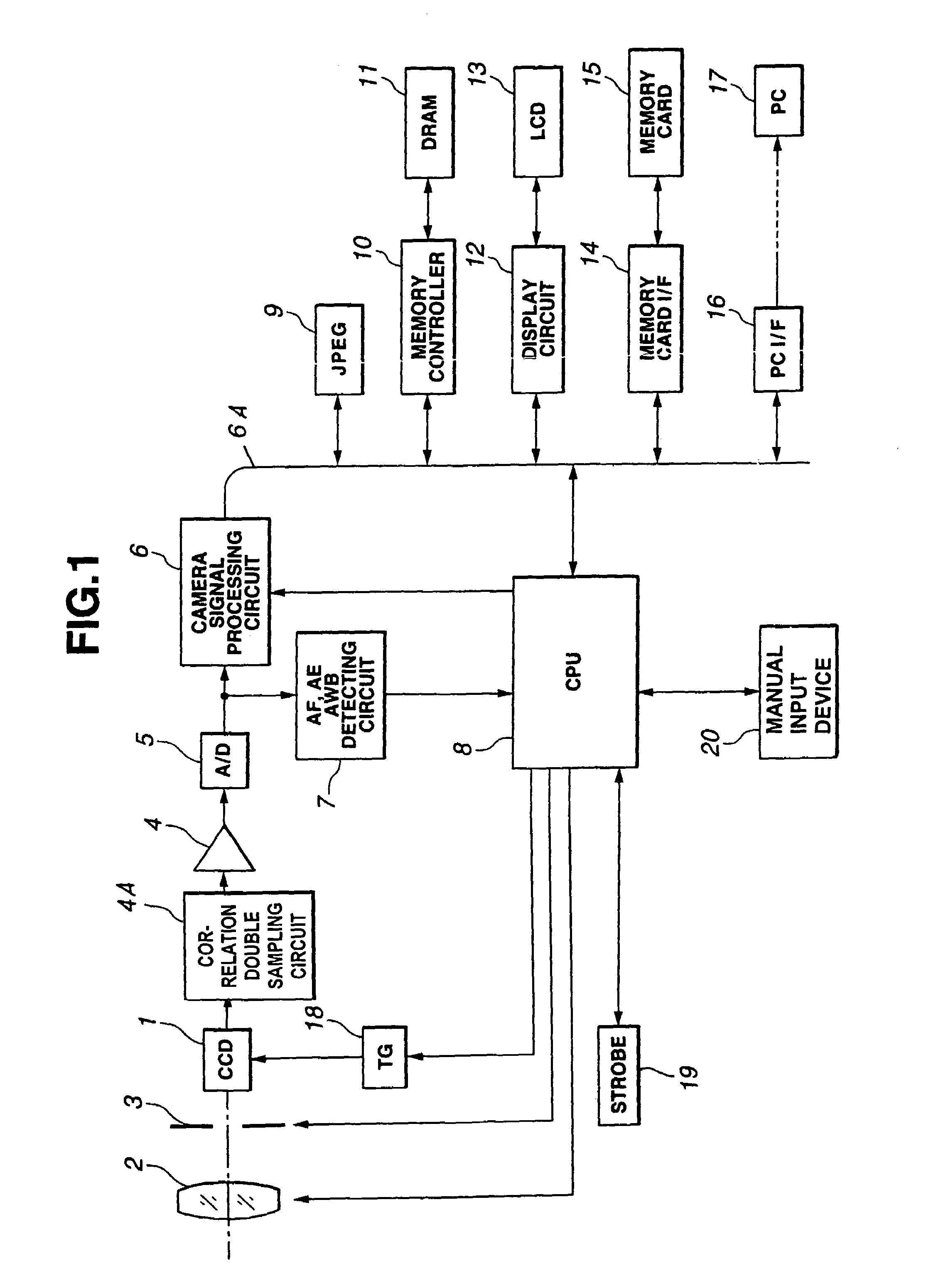
[0039]FIGS. 1 to 9 show the present invention. FIG. 1 is a block diagram showing a fundamental construction of an electric camera. The electric camera according to the invention is comprised of an optical system including a lens 2 and an electric aperture / shutter mechanism 3, an opto-electric image converter 1 such as a CCD for converting the image focused by lens 2 into an electrical image signal, and various signal processing circuits described below, all under control of a CPU 8.

[0040]The signal processing circuits include a noise filter 4A, such as a correlation double sampling circuit, coupled to the output of image converter 1, an amplifier 4 connected to the output of filter 4A, and an A / D converter 5 for digitizing the image signal output of amplifier 4. Connected to the output of A / D converter 5 are a camera signal processor 6, and an AF / AE / AWB detecting circuit 7 for detecting AF (auto focusing) information, AE (auto exposure) information, and AWB (auto white balance) info...

second embodiment

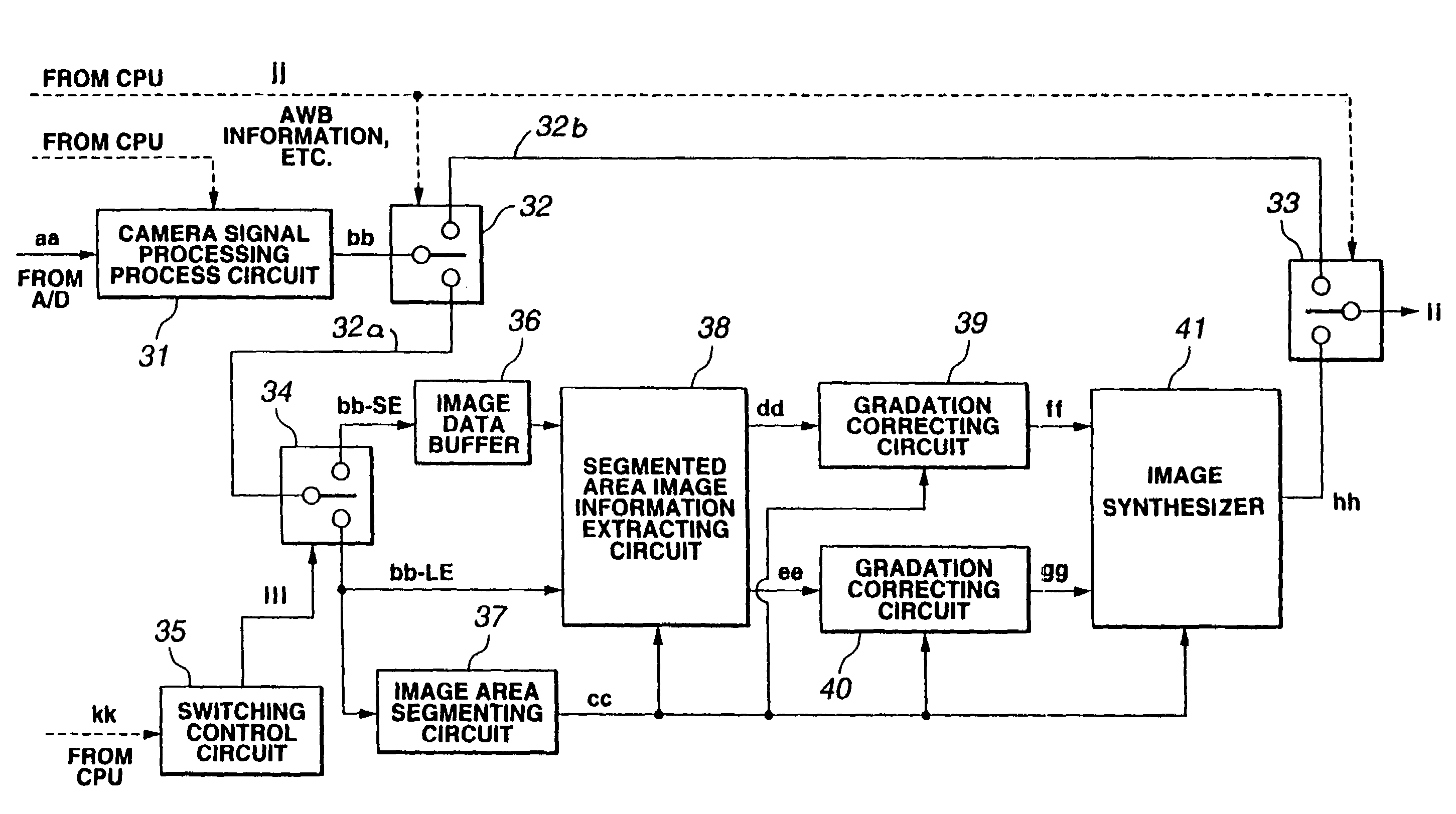
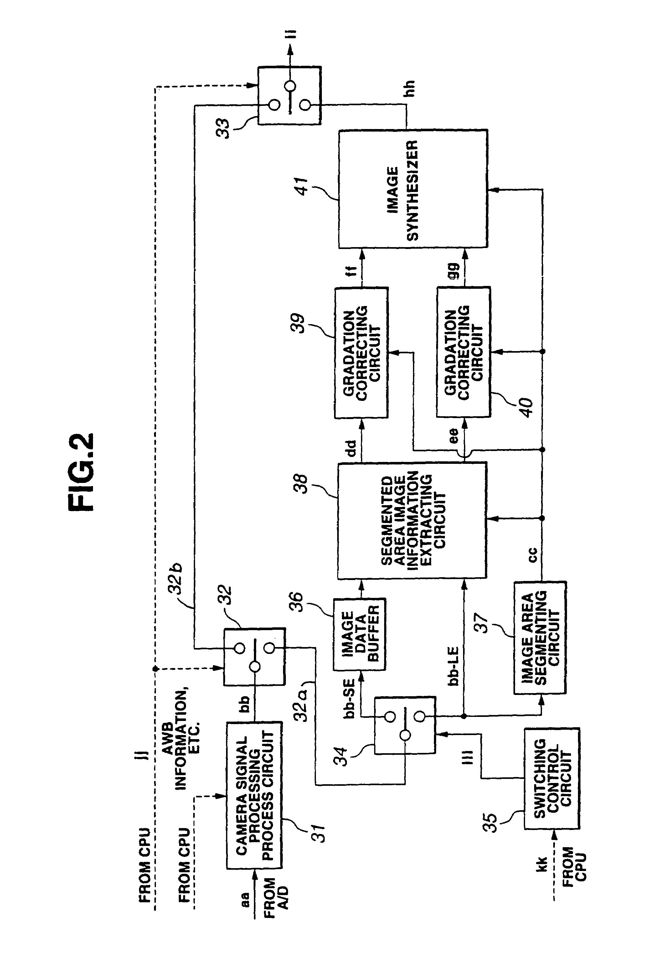
[0112]FIG. 10 is a block diagram showing construction of a camera signal processing circuit according to the Here, an image signal bb-SE representing a short-time exposure is provided from the switch 34 inputted to a Y / C separating circuit 61. An image signal bb-LE representing a long-time exposure LE is provided to a Y / C separating circuit 62.

[0113]The Y / C separating circuits 61 and 62 separate the image signals into a luminance signal Y (referred to as FIG. 12A) and color difference signals Cb and Cr on the basis of r-, g-, and b-components (R, G, and B) in the input image signal according to the following known relationships:

Y=0.29900R+0.58700G+0.14400B  (3)

Cb=31 0.16874R−0.33126g+0.50000B  (4)

Cr=0.50000R−0.41869G−0.08131B  (5)

[0114]Among the above-mentioned separated signals, a luminance signal mm-SE representing the short-time exposure SE is inputted to a feature extracting circuit 63. A luminance signal mm-LE representing the long-time exposure LE is inputted to a feature ext...


PUM


Abstract

An image processing apparatus for generating a wide dynamic range image to enable contrast to be maintained in low luminance image areas and high luminance image areas when the image is displayed by a narrow density range display system having: an image data buffer in which short-time exposure image data is stored; an image area segmenting circuit for fractionating long-time exposure image data into areas of proper and improper exposure; a segmented area image information extracting circuit for segmenting the properly exposed area of the long-time exposure image data on the basis of the segmented information and segmenting the improperly exposed area as a properly exposed area by applying the short-time exposure image data; a gradation correcting circuit for gradation-correcting image data in the properly exposed areas of the long-time exposure and the short-time exposure images which have been segmented by the segmented area image information extracting means, respectively; and an image synthesizer for synthesizing the properly exposed areas after gradation correction to form a composite wide dynamic range image.

Description

CROSS-REFERENCE TO RELATED APPLICATIONS[0001]The present application is a divisional under 37 C.F.R. §1.53(b) of prior application Ser. No. 09 / 451,043 filed Nov. 30, 1999 by Kazuhito HORIUCHI entitled AN IMAGE PROCESSING APPARATUS FOR GENERATING A WIDE DYNAMIC RANGE IMAGE.BACKGROUND OF THE INVENTION[0002]1. Field of the Invention[0003]The present invention relates to an image processing apparatus, more particularly, to an image processing apparatus for generating one wide dynamic range image from a plurality of images photographed under different exposure conditions.[0004]2. Related Art Statement[0005]Conventionally, there have been proposed various image processing apparatuses for synthesizing a plurality of images photographed under different exposure conditions, thereby generating an image having a wide dynamic range. However, when an image having wide dynamic range synthesized by the image processing apparatus is displayed on a monitor or a printer whose density range is relativ...

Claims


Application Information

Patent Timeline
Patent Type & Authority Patents(United States)
IPC IPC(8): H04N5/235H04N1/407
CPCH04N1/4074H04N5/235H04N5/2355H04N23/70H04N23/741
Inventor HORIUCHI, KAZUHITO
Owner OLYMPUS CORP
Why Eureka
Try Eureka