Projection subsystem for high contrast projection system

a projection system and projection subsystem technology, applied in the field of projection subsystems for high contrast projection systems, can solve the problems of increasing the cost of pj lenses, reducing the efficiency of light isolation design, and longer backworking distance of projection lenses, so as to maintain the contrast of high contrast projection systems

Active Publication Date: 2018-04-03
BARCO NV
View PDF15 Cites 9 Cited by
  • Summary
  • Abstract
  • Description
  • Claims
  • Application Information

AI Technical Summary

Benefits of technology

[0013]An object of the present invention is that at least some embodiments provide a simple yet efficient prism assembly and recombination device that will maintain the contrast of high contrast projection system and that can be used with the new generation of TRP micro mirror devices.
[0022]The first TIR surface is adapted to reflect the unwanted light reflected from the OFF pixels and FLAT pixels of said MMD passing through said first prism 1. The unwanted light strikes said first TIR surface at an angle greater than the critical angle of said TIR surface and is immediately reflected off said first TIR surface away from said projection path, into an heat sink, thereby separating unwanted light from projected light (that is light reflected by ON pixels), increasing the contrast of the projection system. Unwanted light is not limited to the light reflected by FLAT and OFF pixels, unwanted light is also reflected from flat surfaces and edges, in, around, and under the pixels or micro mirrors of said MMD passing through said first prism 1. As with the light reflected off FLAT and OFF pixels, said light strike the first TIR surface at an angle greater than the critical angle of said TIR surface and is immediately reflected off said first TIR surface away from said projection path, into an heat sink, thereby separating said unwanted light from said projected light, increasing the contrast of the projection system.
[0024]The use of TRP with bottom illumination makes the structure compact. For an FTP structure with a Manhattan type pixel design, i.e. illumination happens in the diagonal direction on the pixel structure, the whole TIR structure has to be put at a 45° angle, which will make it bigger, as the area in between the vertices mentioned above has to be made bigger.

Problems solved by technology

With the arrival of the new type of micro mirror devices, where a new type of micro-mirror known as Tilt-and-Roll Pixel (TRP) is used, it has become even more challenging to design prism assemblies that will efficiently isolate the light reflected by ON pixels from unwanted light reflected by the micro mirror devices.
In the case of a 3 chips projector, the Philips prism architecture is a very popular one, but its use with TRP DMD's raises additional problems as well:The incidence angle of the illumination light cone must now be 34 degrees (in air) instead of 24 degrees.
As a consequence, the “dichroic shift” phenomenon, responsible of big light losses in the Philips prism assembly, and caused by the different incidence angle, onto the dichroic mirrors, for the illumination light and the ON state light will be even more severe with TRP chips than with FTP chips.For the same reason, a redesign of the TIR prism will be necessary (other angles), unevitably leading to a bigger assembly and thus to a longer backworking distance for the projection lens (increasing the PJ lens cost).

Method used


Image

  • Projection subsystem for high contrast projection system
  • Projection subsystem for high contrast projection system
  • Projection subsystem for high contrast projection system

Examples


specific embodiment

[0097]The following is a specific embodiment of the present invention which is non-limiting.

[0098]Materials used: Glass type is BK7 or similar, with a refraction index varying from 1.514 to 1.528 over the useful wavelength range. The highest index value corresponds to the shortest wavelength.

[0099]Only a fraction of the etendue is used and the F / number is limited to F / 2.4 instead of the “usable” F / 1.7.

[0100]The half cone angle is 12 degrees in air for the illumination, the ON-state, the flat state and the OFF-state.

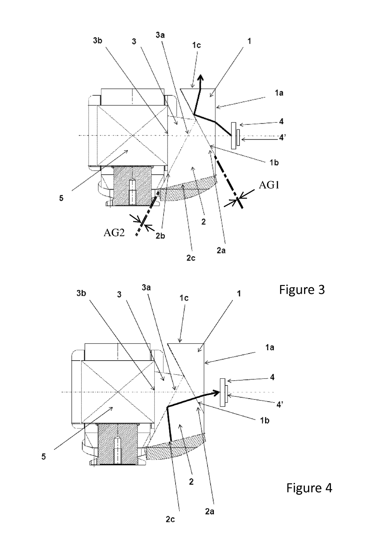
[0101]The lowest ray in the ON-state cone (the ray with the biggest incidence angle on the TIR surface 2c) reaches the TIR surface 2c at an incidence angle equal to the critical angle when the TIR angle A is equal to 33.45° for n=1.514 and 33.06° for n=1.528.

[0102]The maximum A value (see picture below) that will ensure that all the ON-state rays of all useful wavelengths will pass through the TIR surface 2c is thus 33.06°

[0103]The highest ray in the illumination cone (th...


PUM


Abstract

A projection subsystem for a high contrast projection system is described including three digital micro-mirror devices (MMD) and three prism assemblies and a crossed dichroic prism assembly, the prism assemblies having dual TIR prisms.

Description

[0001]The present invention relates to projector subsystems and projectors having a prism assembly and a recombination device such as projection systems which recombine the light reflected off several digital micro mirror devices with a dichroic combiner also known as cross dichroic assembly or X-cube.BACKGROUND OF INVENTION[0002]Existing projection systems equipped with three micro mirror devices make extensive use of so called Philips prism assemblies to illuminate the micro-mirror devices and to combine the fundamental colours reflected by the micro-mirror devices.[0003]Prism assemblies in these projectors must be designed carefully to prevent light not selected to be projected (i.e. light reflected by pixels in another state than the ON state as well as light reflected by edges and surfaces next to and under the pixels of the micro-mirror devices) to ruin the contrast of the projection system.[0004]One type of micro mirror device is an FTP DMD, in the micro-mirrors can be tilted...

Claims


Application Information

Patent Timeline
Patent Type & Authority Patents(United States)
IPC IPC(8): G03B21/28H04N9/31G02B27/14H04N5/74G03B21/20G03B21/00G02B27/10G03B33/12
CPCG03B33/12G02B27/1026G02B27/1066G02B27/149H04N9/3164G03B21/2033G03B21/28H04N5/7458H04N9/3105G03B21/008
Inventor LAMBOT, DANIEL
Owner BARCO NV
Why Eureka
Try Eureka