Method of mapping source colors of a source content

a source content and color gamut technology, applied in the field of color gamut mapping, can solve the problems of not being able to reproduce the mastering display device, the color space was shown to not well represent all hues, and the color space was not well represented by the color space, etc., to achieve the effect of affecting the intensity and contrast of colors and the overall contras

Inactive Publication Date: 2017-04-27
THOMSON LICENSING SA
View PDF10 Cites 9 Cited by
  • Summary
  • Abstract
  • Description
  • Claims
  • Application Information

AI Technical Summary

Benefits of technology

[0047]The second transform according to the general embodiment illustrated on FIG. 4 does require processing only for very few colors since the source colors are by definition within the mastering display color gamut and the virtual display color gamut is very close to the mastering display color gamut since the virtual display has the same primaries than the mastering display color gamut.
[0048]In a first variation, the virtual display device is further characterized by an EOTF corresponding to that of a mastering display device used to master said source content, preferably further characterized by a white point corresponding to that of said mastering display device. It then means that the application of said virtual display inverse color transform is closed to the application of the mastering display inverse color transform characterizing this mastering display device.
[0049]FIG. 7 illustrates this first variation of the method illustrated in FIG. 4, in which the virtual display device is also defined by its white point and its EOTFs. This variation is characterized in that the virtual display has the same white point and the same EOTFs as the mastering display device. In general, the white point of a display is the color that a display produces if it is controlled by device dependent color coordinates that are all at maximum signal level. In general, the electro-optical transfer function (EOTF) of a display device is the relation between the luminance produced by a display with respect to the signal levels of color coordinates R, G and B applied to the different color channels used to control this display device. As reminded above in reference to PLCC and RP177 models, an additive, trichromatic display device is notably characterized by three EOTFs, one for each color channel. The first EOTF defines the contribution of given R on X,Y,Z when G and B are set to minimum signal level. The second EOTF defines the contribution of given G on X,Y,Z when R and B are set to minimum signal level. The third EOTF defines the contribution of given B when R and G are set to minimum signal level. The three EOTFs can be identical, such as defined for example by the standard ITU-R BT.2020.
[0050]In a second variation, said virtual display device is further characterized by an EOTF corresponding to that of said reference display device, preferably further characterized by a white point corresponding to that of said reference display device. FIG. 8 illustrates this second variation of the method illustrated on FIG. 4. This variation is characterized in that the virtual display device has the same white point and the same EOTFs as the reference display device although its primaries are still those of the mastering display device. In this way, the virtual display has hybrid characteristics, partly from the mastering display—for the primary colors—and partly from the reference display—for EOTF and white point.
[0051]As a variant, the virtual display may have additional characteristics such as cross channel non-linearities, as opposed to additive displays which have no cross channel non-linearities and are fully defined by the three primary colors, the white point and the three EOTFs (see PLCC and RP177 models above). Here, such cross channel non-linearities is the non-linear, cross influence of two color coordinates on the reproduced color.
[0052]There are several advantages of this second variation shown in FIG. 8 of the method illustrated in FIG. 4. A first advantage is, as already mentioned, that source colors within a mastering display color gamut are transformed into mapped colors that are approximately still within the color gamut of the reference display. A second advantage is that such a mapping does not change the white point as well as the overall contrast of the content. As mentioned, the white point is the color that a display produces if it is controlled by device dependent color coordinates that are all at maximum signal level. Since the virtual display has the same white point as the reference display, the mapping outputs color coordinates R′,G′,B′ each at maximum signal level when the input color coordinates R,G,B are each at maximum signal level. If the white point is defined only by its chromaticity coordinates but not by its amplitude or intensity, this relation still applies up to a scaling factor. The EOTF mainly impacts the intensity and contrast of colors. If a trichromatic display device is characterized by three different EOTFs, the EOTFs impact also the hue and the saturation of colors. Since the EOTFs of the virtual display device are identical to those of the reference display device, the EOTFs will not cause a change of hue and saturation of colors. Additionally, the overall contrast is preserved, too. For example, a grey ramp of colors is not modified and thus preserved by this second variation.

Problems solved by technology

Gamut mapping is usually more complex than just clipping.
Unfortunately, this color space was shown to not well represent all hues, notably in blue tones.
It might occur that some colors (notably luminances of these colors) of the HDR content encoded according to this HDR standard are not actually used during the mastering, notably because some colors (notably luminances) of the HDR content that can be encoded according to this HDR standard cannot be reproduced by the mastering display device, i.e. by the LCD monitor.
Second, the color gamut used for the encoding and / or the transmission of the UHDTV or HDR content.
Third, the target color gamut of the device used for the reproduction of the content after decoding, here the consumer TV set.

Method used


Image

  • Method of mapping source colors of a source content
  • Method of mapping source colors of a source content
  • Method of mapping source colors of a source content

Examples


Embodiment Construction

[0104]It will be appreciated by those skilled in the art that block diagrams and the like presented herein represent conceptual views of illustrative circuitry embodying the invention. They may be substantially represented in computer readable media and so executed by a computer or processor, whether or not such computer or processor is explicitly shown.

[0105]The functions of the various elements shown in the figures may be provided through the use of dedicated hardware as well as hardware capable of executing software in association with appropriate software.

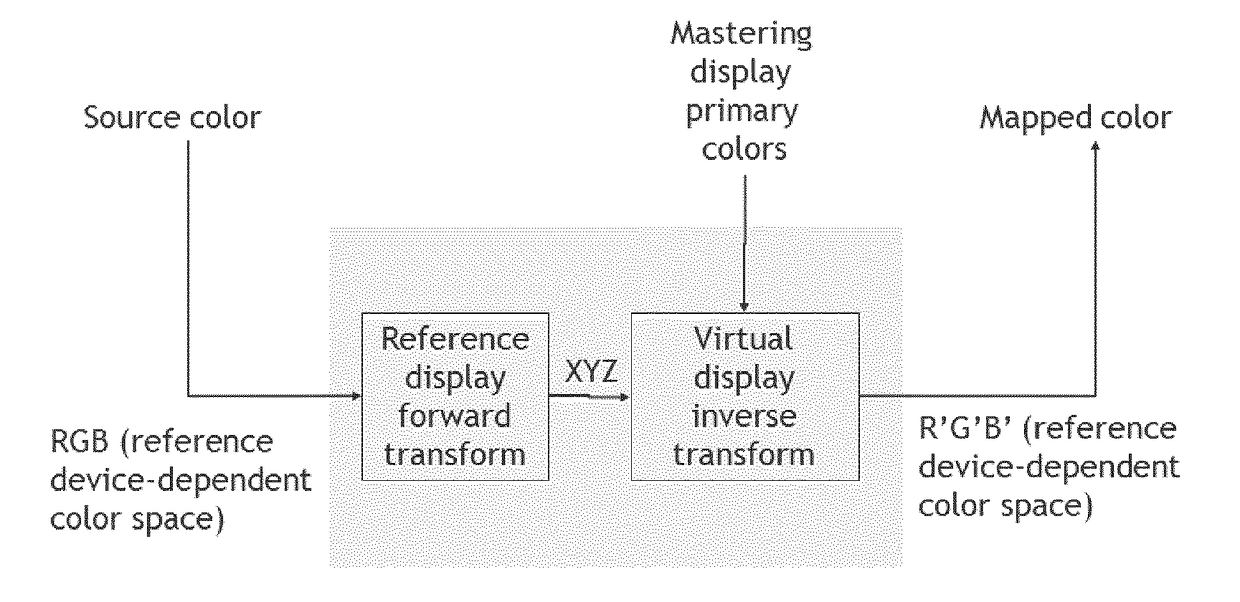
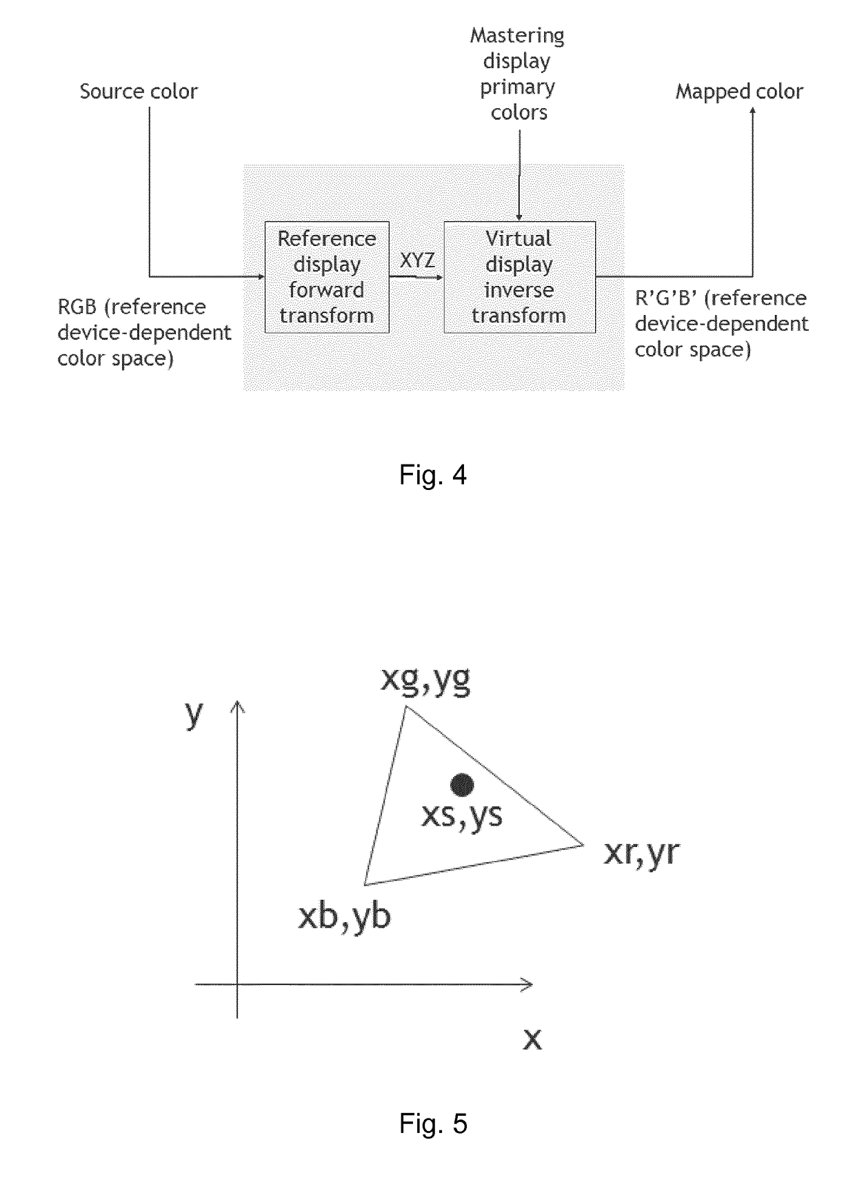
[0106]A source content is provided but is formatted to be reproduced by a reference display device, for instance as standardized according to ITU-R BT.2020, i.e. based on a wide color gamut. This source content has been mastered on a given mastering display device, notably characterized by given color primaries.

[0107]We will now describe how such source colors could be advantageously mapped into mapped colors adapted to be repr...


PUM


Abstract

Method of mapping source colors of a source content represented by source coordinates comprising: —applying a reference display forward color transform characterizing a reference display device, —applying a virtual display inverse color transform configured to model a virtual display device having approximately the same color primaries as a mastering display device used to master said source content.

Description

TECHNICAL FIELD[0001]The invention is in the field of methods and systems for color correcting to provide predictable results on displays with different color gamuts. The invention concerns notably a method for color gamut mapping using linear models and metadata on the color gamut.BACKGROUND ART[0002]When images are created in motion picture, broadcast or other video workflows, the color of the images is verified using a mastering display while finally the images will be watched on other displays, for example in theatres, on TV screens or on a tablet.[0003]For example, a graphics arts creator verifies the colors on the monitor of his workstation while the final reproduction will be printed on paper. In this case, the workstation monitor is the mastering display device and the paper printer is the final reproduction device. Another example is capture of images on argentic film, scanning images of this film and color correction of the scanned images. The film is scanned using a dedic...

Claims


Application Information

Patent Timeline
Patent Type & Authority Applications(United States)
IPC IPC(8): G09G5/02H04N9/12H04N1/60
CPCG09G5/02H04N1/6066G09G2320/0673G09G2340/06H04N9/12
Inventor STAUDER, JURGENKERVEC, JONATHANGARCIA CAPEL, LUIS EDUARDO
Owner THOMSON LICENSING SA
Why Eureka
Try Eureka