Method and apparatus for performing a charging process on an image carrying device

a charging process and image technology, applied in the direction of corona discharge, textile selvedges, instruments, etc., can solve the problems of affecting the formation of images, nox, ozone, etc., and causing the image to be dirty,

Inactive Publication Date: 2005-12-20
RICOH KK
View PDF19 Cites 11 Cited by
  • Summary
  • Abstract
  • Description
  • Claims
  • Application Information

AI Technical Summary

Benefits of technology

[0040]Each of short side edges of each of the film members may have an edge line with an acute angle relative to an edge of a longitudinal side of the each of the film members to form an acute triangle such that the edge lines of the short side edges face each other to form a thin-line-shaped space therebetween. In one embodiment, the acute angle is approximately 45 degrees.

Problems solved by technology

The above corona charge apparatus, however, has a drawback in that various discharge products such as ozone, NOx, etc. are produced due to the relatively high voltage applied.
This results in environmental pollution and also causes problems with the image forming process in that the discharge products often produce a coat of nitric acid or nitrate which adversely affects formation of the image.
This results in a dirty mark on an image.
This causes a deterioration of charging performance.
However, it is difficult to evenly increase diameters of both ends of the charge roller which is covered by the elastic member, by wrapping a film, for example, around the ends of the wrapping elastic member.
Therefore, when using a relatively thin film, the charge roller which is the non-contact type charge roller has a risk at the center portion thereof to contact the surface of the photoconductive member.
However, an increase in film thickness will make the gap G greater, in particular, around the positions close to the films, resulting in abnormal discharge.
In this case, abnormal discharge may occur when the voltage applied according to the gap is too large.
The above-described image forming apparatus described in the published Japanese unexamined patent application No. 7-121002, has a drawback.
But, this makes it difficult to maintain the straightness of the relatively long surface of the photoconductive drum within a desired tolerance and therefore the manufacturing cost is increased.
Thus, the transfer roller is prone to be worn at both ends and a leak of the charge at the ends thereof which are worn will occur.
At the same time, the film members themselves will be worn and, as a result the gap for assuring the desirable charging performance cannot be formed.
Therefore, the cleaning member is prone to wearing at both ends, causing leakage of the charge at the ends which are worn.
If a cleaning member is not provided and the charging member is deposited with the residual toner, this causes a reduction of the charging performance and results in production of an abnormal image.
However, this will cause a problem in some cases.

Method used


Image

  • Method and apparatus for performing a charging process on an image carrying device
  • Method and apparatus for performing a charging process on an image carrying device
  • Method and apparatus for performing a charging process on an image carrying device

Examples


Embodiment Construction

[0080]In describing preferred embodiments illustrated in the drawings, specific terminology is employed for the sake of clarity. However, the invention is not intended to be limited to the specific terminology so selected and it is to be understood that each specific element includes all technical equivalents which operate in a similar manner.

[0081]Referring now to the drawings, wherein like reference numeral designate identical or corresponding parts throughout the several views, and more particularly to FIGS. 1–4, a charge roller 14 according to an embodiment of the present invention is described.

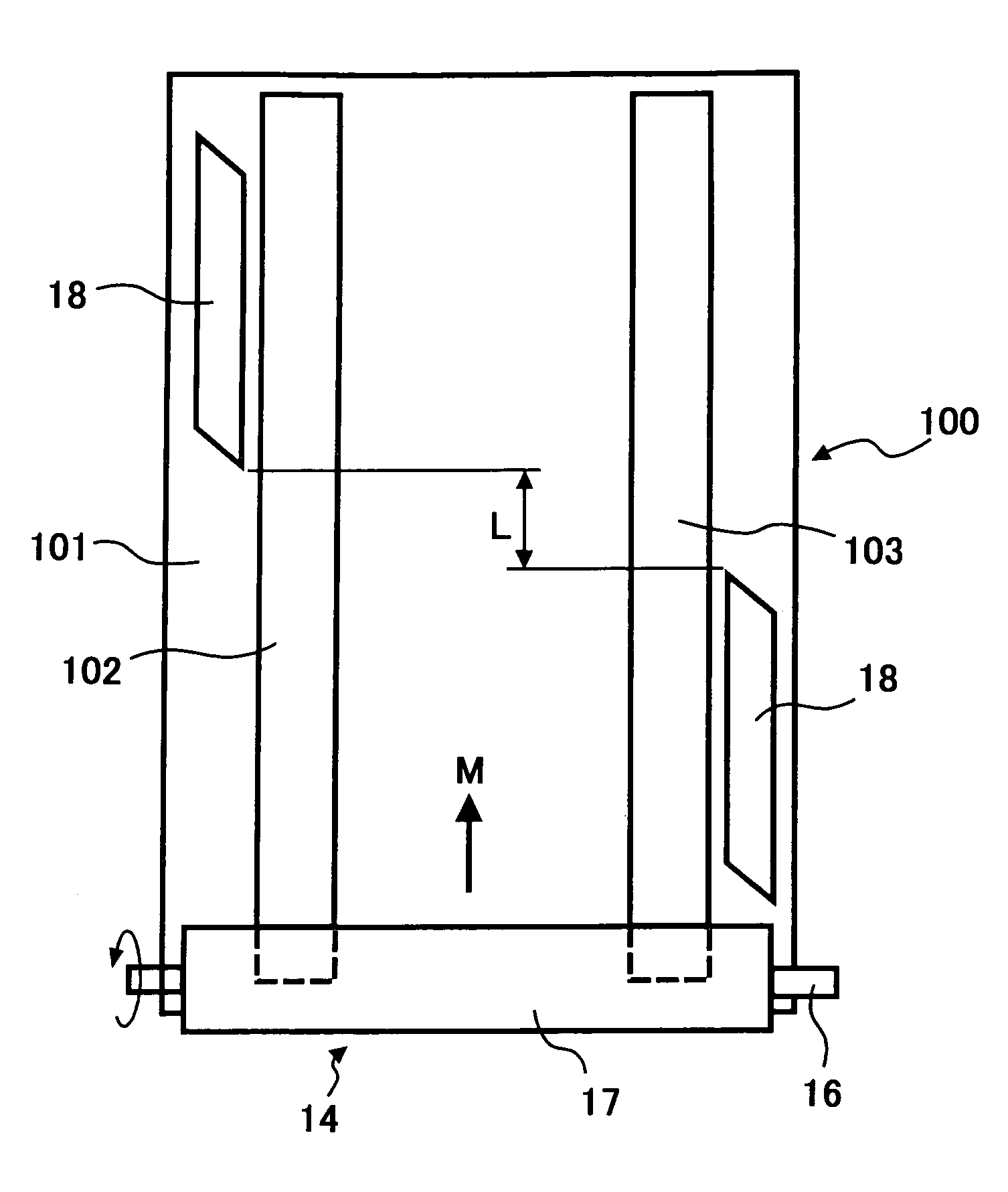
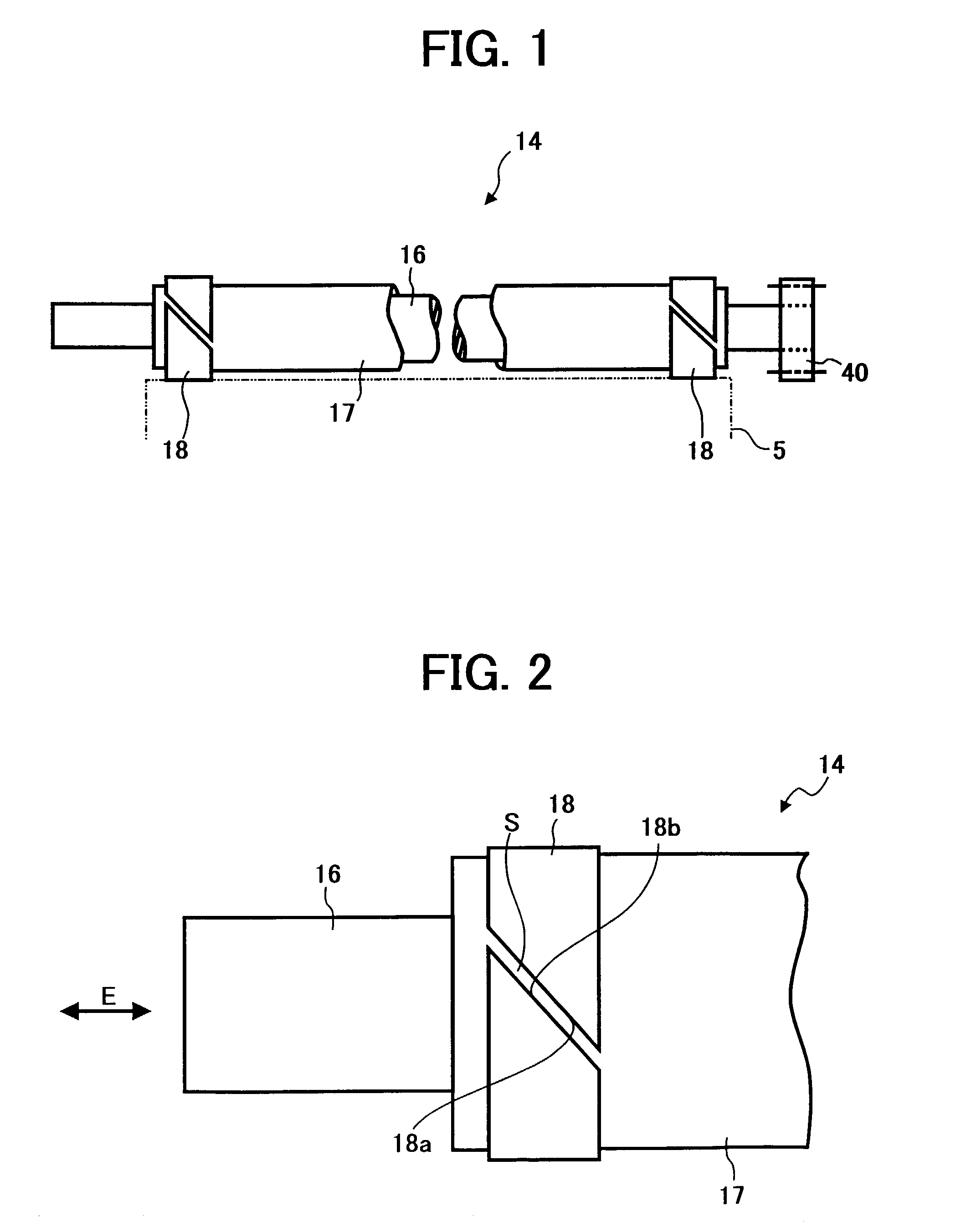
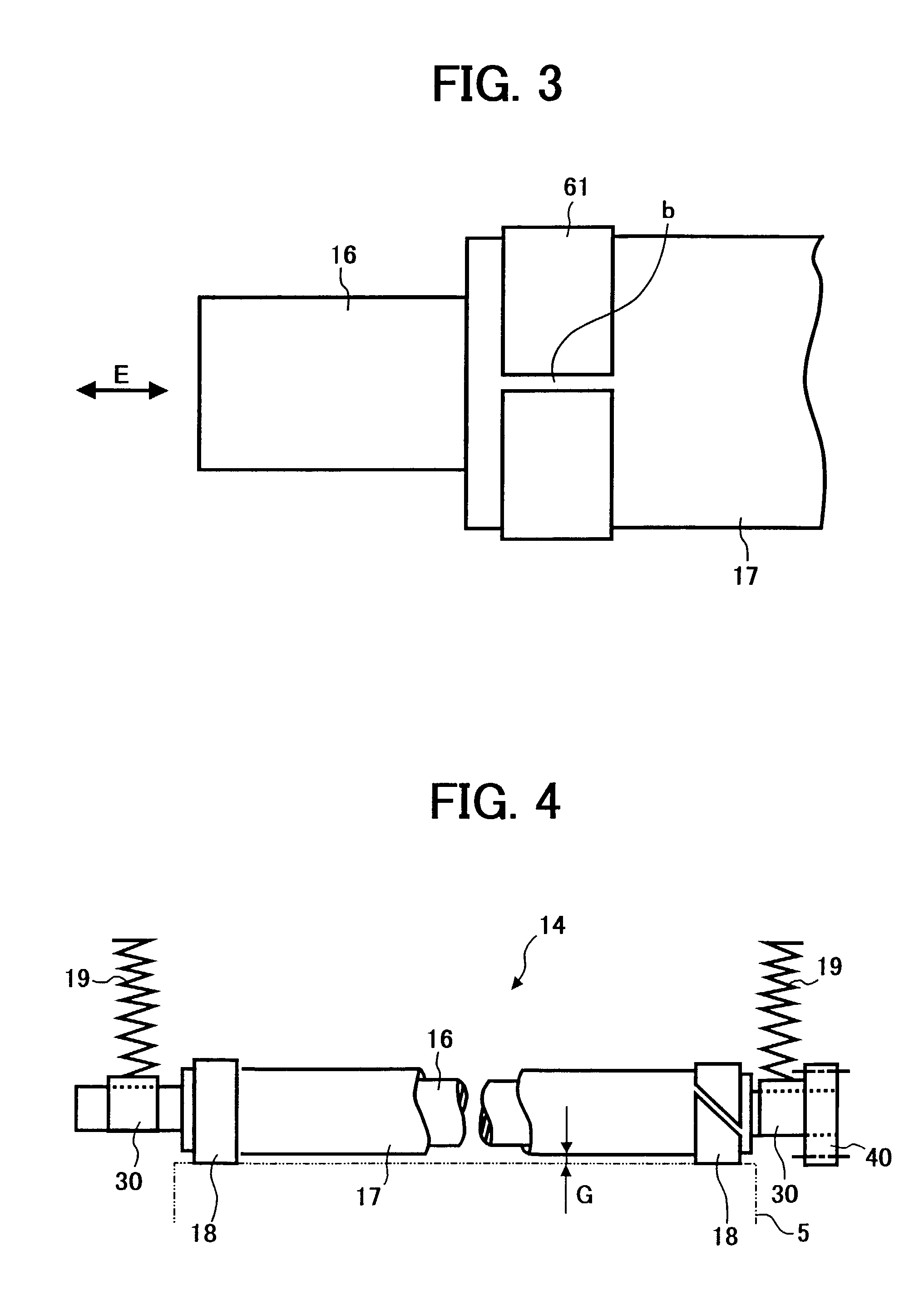
[0082]The charge roller 14 of FIG. 1, a charged roller, is arranged next to a photoconductive drum 5 which receives a charge from the charge roller 14 and is applied with a voltage by a power supply source. The photoconductive drum 5 is also referred to as an image carrying member. The charge roller 14 includes a nickel-plated metal core 16 and an elastic member 17 that covers the metal c...


PUM

PropertyMeasurementUnit
widthaaaaaaaaaa
sizeaaaaaaaaaa
widthaaaaaaaaaa

Abstract

A charge roller that includes a metal core, an elastic member configured wrapped around the metal core, and film members is disclosed. Each of the film members is wrapped around each end of the elastic member in a circumferential direction of the metal core such that at least a part of each of the film members exists at every position around the ends of the elastic member in an axial direction of the metal core. Portions of the film members do not overlap each other in an radial direction of the metal core.

Description

CROSS-REFERENCES TO RELATED APPLICATIONS[0001]This application claims priority to Japanese patent application Nos. JPAP2000-030908 (filed Feb. 8, 2000) and JPAP2001-24007 (filed Jan. 31, 2001), both of which are incorporated herein by reference.BACKGROUND OF THE INVENTION[0002]1. Field of the Invention[0003]The present invention relates to a method and apparatus for roller charging, and more particularly to a method and apparatus for performing a charging process relative to an image carrying member in an electrophotographic image forming process.[0004]2. Discussion of the Background[0005]Conventionally, electrophotographic image forming apparatuses such as copying machines, printers, facsimile machines, and so on use a variety of ways for evenly applying a charge to a photoconductive member before generating an electrostatic latent image.[0006]In one exemplary way, a corona discharge is used. A corona charge apparatus includes a charge wire made of tungsten or nickel and which is e...

Claims


Application Information

Patent Timeline
Patent Type & Authority Patents(United States)
IPC IPC(8): F16C13/00G03G15/02G03G21/10
CPCG03G15/0208G03G15/0233G03G15/025Y10T428/24355Y10T428/25Y10T428/1376
Inventor SATO, MASUMIYOSHINAGA, HIROSHIIWASAKI, YUKIKOISHIBASHI, HITOSHIFUJISHIRO, TAKATSUGUHIRAMATSU, MASAMIHIRANO, HIROKO
Owner RICOH KK
Why Eureka
Try Eureka