
Method and assembly of sensor ready tires

a technology of sensor and assembly method, which is applied in the direction of vehicle tyre testing, instruments, roads, etc., can solve the problems of electronic tag and the connection between the tag and the antenna, in particular, being vulnerable to damage, and being difficult to do, so as to facilitate the post-cure location of the overlap region

Inactive Publication Date: 2005-12-27
THE GOODYEAR TIRE & RUBBER CO
View PDF11 Cites 21 Cited by
  • Summary
  • Abstract
  • Description
  • Claims
  • Application Information

AI Technical Summary

Benefits of technology

This approach securely attaches the antenna to the tire while protecting electronics from manufacturing stresses, reducing labor and material costs, and ensuring a reliable electrical connection without compromising tire integrity.

Problems solved by technology

In practice, however, it is very difficult to do this.
An annular antenna and the electronic tag associated therewith built into the tire in a pre-cure process, therefore, must endure significant stresses that can result in component failure.
The electronic tag and the connection between the tag and the antenna, in particular, is vulnerable to damage from the forces imposed from pre-cure assembly to tire.
First, the procedure adds labor, and hence cost, to the manufacturing process.
Secondly, the security of the attachment between the annular apparatus and the tire is dependent upon the efficacy of the adhesive system employed.
Development of a suitable adhesive that is inexpensive, convenient to use, and durable enough to function throughout the life cycle of a tire has proven problematic.

Method used


Image

  • Method and assembly of sensor ready tires
  • Method and assembly of sensor ready tires
  • Method and assembly of sensor ready tires

Examples


Embodiment Construction

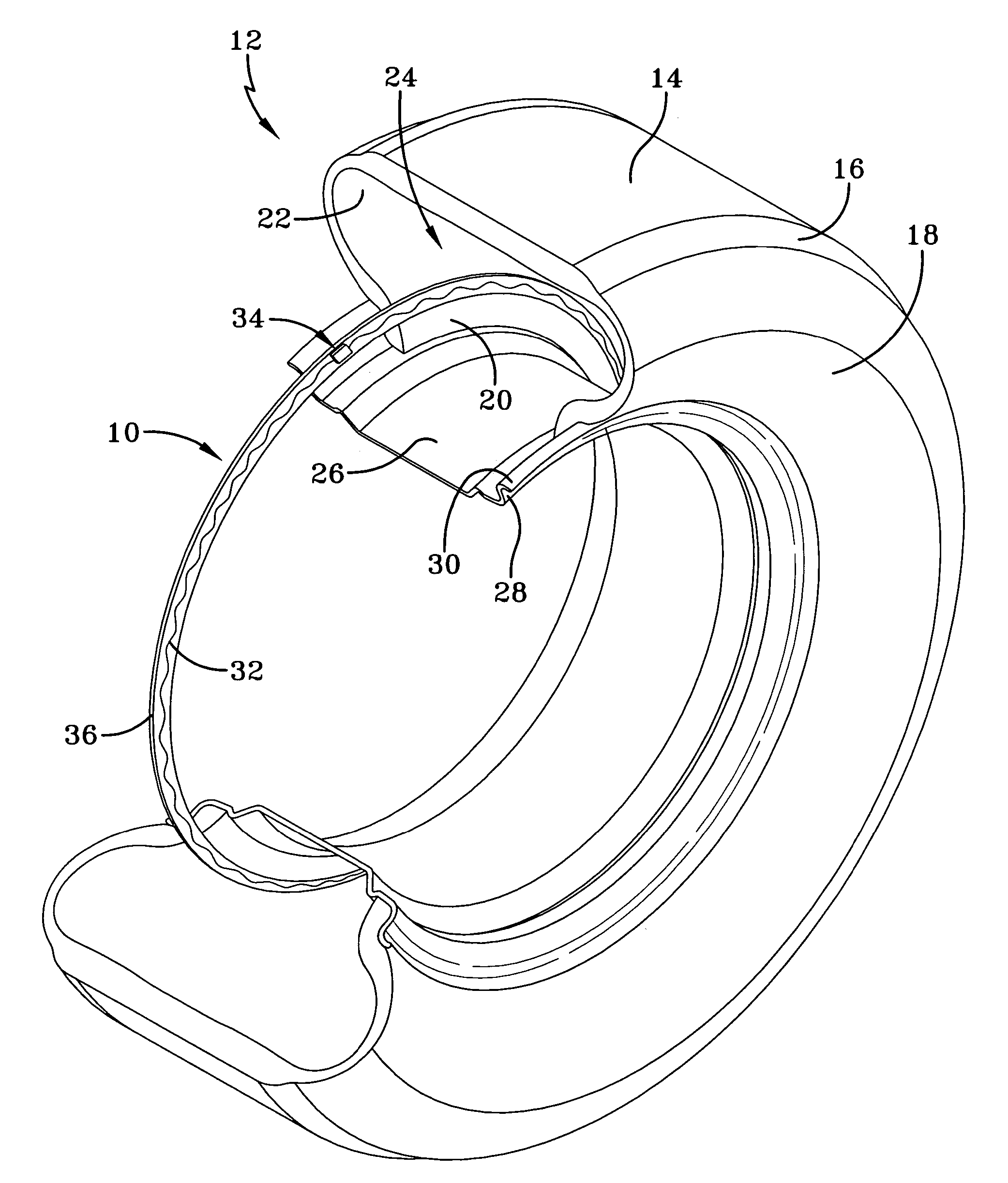
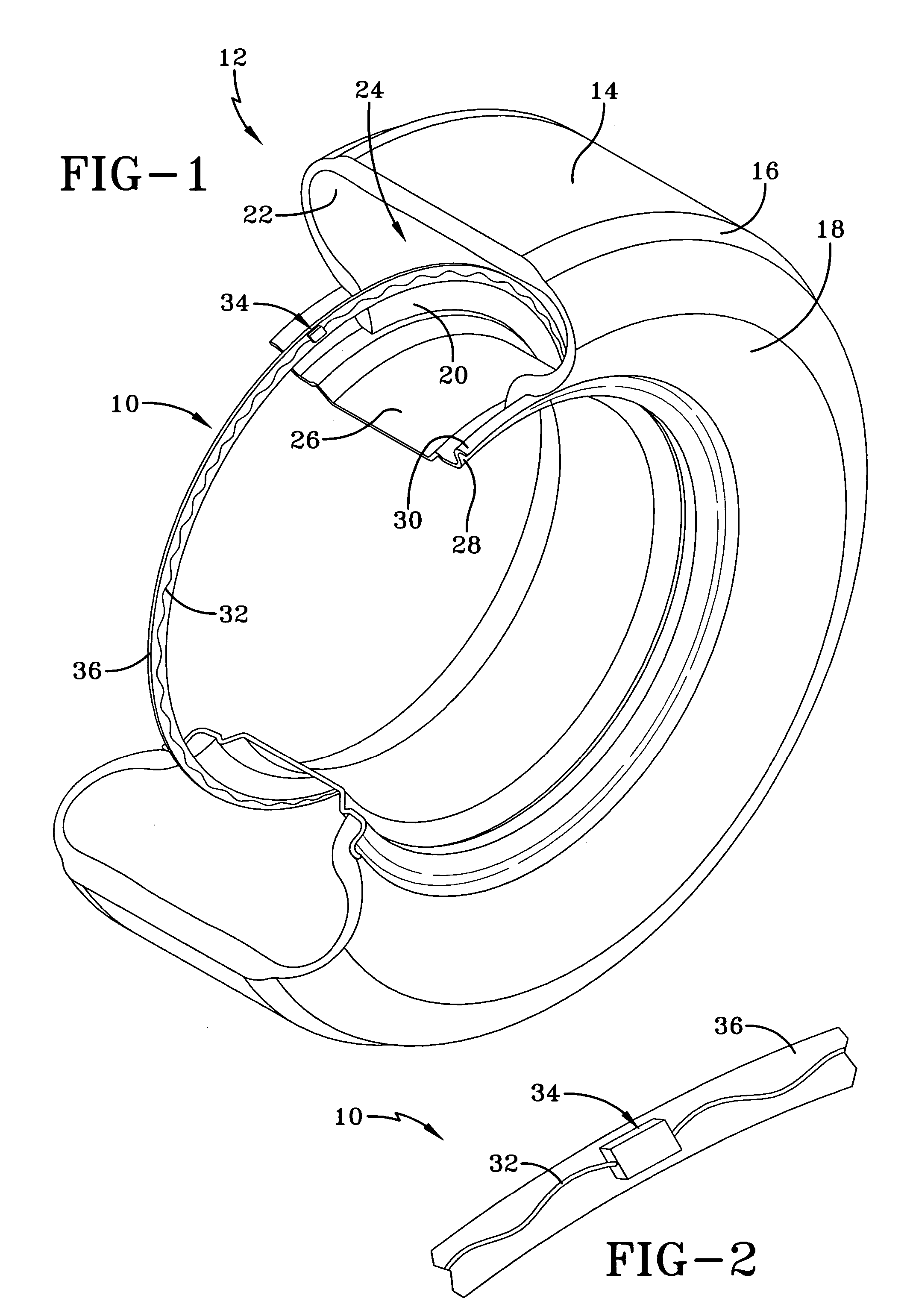
[0013]Referring initially to FIGS. 1 and 2, a preferred embodiment 10 of the subject invention is shown deployed within a tire 12. The tire 12 is formed from conventional materials such as rubber or rubber composites by conventional means and may comprise a radial ply or bias ply configuration. A typical tire 12 is configured having a tread 14, a shoulder 16, an annular sidewall 18, and a terminal bead 20. An inner liner 22 is formed and defines a tire cavity 24. The tire 12 is intended for mounted location upon an annular rim 26 having a peripheral rim flange 28 and an outer rim flange surface 30. Rim 26 is conventionally configured and composed of a suitably strong metal such as steel.

[0014]An annular antenna 32 is provided and, in the preferred embodiment, embodies a sinusoidal configuration. Antenna 32 may be alternatively configured into alternative patterns or comprise a straight wire(s) if desired and may be filament wire, or cord or stranded wire. Antenna 32 may be incorpora...


PUM

PropertyMeasurementUnit
shapeaaaaaaaaaa
radio frequencyaaaaaaaaaa
pressureaaaaaaaaaa

Abstract

Apparatus and method for post-cure application of electronics to a tire includes the steps: forming an antenna wire into a predetermined shape having first and second free ends; creating a transponder splice region between the first and second free antenna ends, incorporating transponder splice region identification indicia; curing the antenna wire into a tire during a tire manufacturing procedure; locating the transponder splice region by means of the transponder splice region identification indicia; and splicing the antenna wire ends to a sensor in a post-cure procedure. The transponder splice region identification indicia may include sandwiching a junction box or the overlapped ends of the antenna wire or wires between layers of select material that will not bond to the tire inner liner or antenna cover compounds and incorporating an air pocket in the sandwiched region. Alternatively, or in conjunction with the air pocket, a unique cover layer differentiated by color or other discernible means may be utilized to seal and cover the transponder splice region.

Description

FIELD OF THE INVENTION[0001]The subject invention relates generally to systems and methods for applying electronics to a tire for the purpose of monitoring tire condition parameters and, more specifically, to an assembly and method for manufacturing a sensor-ready tire so as to facilitate a post-cure incorporation of a sensor in the tire.BACKGROUND OF THE INVENTION[0002]It is common to employ annular apparatus, including an antenna, for electronically transmitting tire or wheel identification or other data at radio frequency. Sensors used inside tires for the measurement of internal air pressure and temperature or strain sensors require attachment to an antenna that forms a complete circumferential loop within the tire. A complete loop is required for reading and powering the sensor in all tire positions and whether the tire is stationary or rotating. Typically, the apparatus includes a radio-frequency tag, or transponder, comprising an integrated circuit chip having data capacity a...

Claims


Application Information

Patent Timeline
Patent Type & Authority Patents(United States)
IPC IPC(8): B29D30/06B60C19/00G08C19/00B60C23/04B60C23/20G08C17/02H01Q1/22
CPCB60C23/0493H01Q1/22H01Q1/2241
Inventor LIONETTI, ROBERT EDWARDLAMBE, ROBERT
Owner THE GOODYEAR TIRE & RUBBER CO
Learn More