Emergency pressure relief valve with enhanced reset

a technology of pressure relief valve and emergency valve, which is applied in the field of valves, can solve the problems of excessive valve wear, undesirable operation method, and use of these valves

Active Publication Date: 2005-12-27
SPM OIL & GAS INC
View PDF21 Cites 32 Cited by
  • Summary
  • Abstract
  • Description
  • Claims
  • Application Information

AI Technical Summary

Benefits of technology

[0014]As the piston and valve member initially return to the closed position, the fluid flows from the portion of the chamber below the piston. Preferably, the fluid beneath the piston travels from below the piston into the chamber above the piston by way of a check valve carried by the piston. As the piston and valve member continue to return to the closed position, the fluid below the piston is exposed to a port that allows the fluid to vent from the area below the piston. Venting the fluid helps the piston and valve member fully return or land in a valve seat of the pressure relief valve.

Problems solved by technology

A problem sometimes develops in the use of these valves in systems that experience rapidly varying pressures.
This method of operation is undesirable when the pressure of the system fluid varies rapidly.
The rapid movement of the valve member within the housing causes excessive valve wear and excessive heat to be generated, both of which are undesirable features.
The problem with this type of valve is that it requires extensive operator monitoring and involvement when the pressure of the system fluid varies rapidly.

Method used


Image

  • Emergency pressure relief valve with enhanced reset
  • Emergency pressure relief valve with enhanced reset
  • Emergency pressure relief valve with enhanced reset

Examples


Embodiment Construction

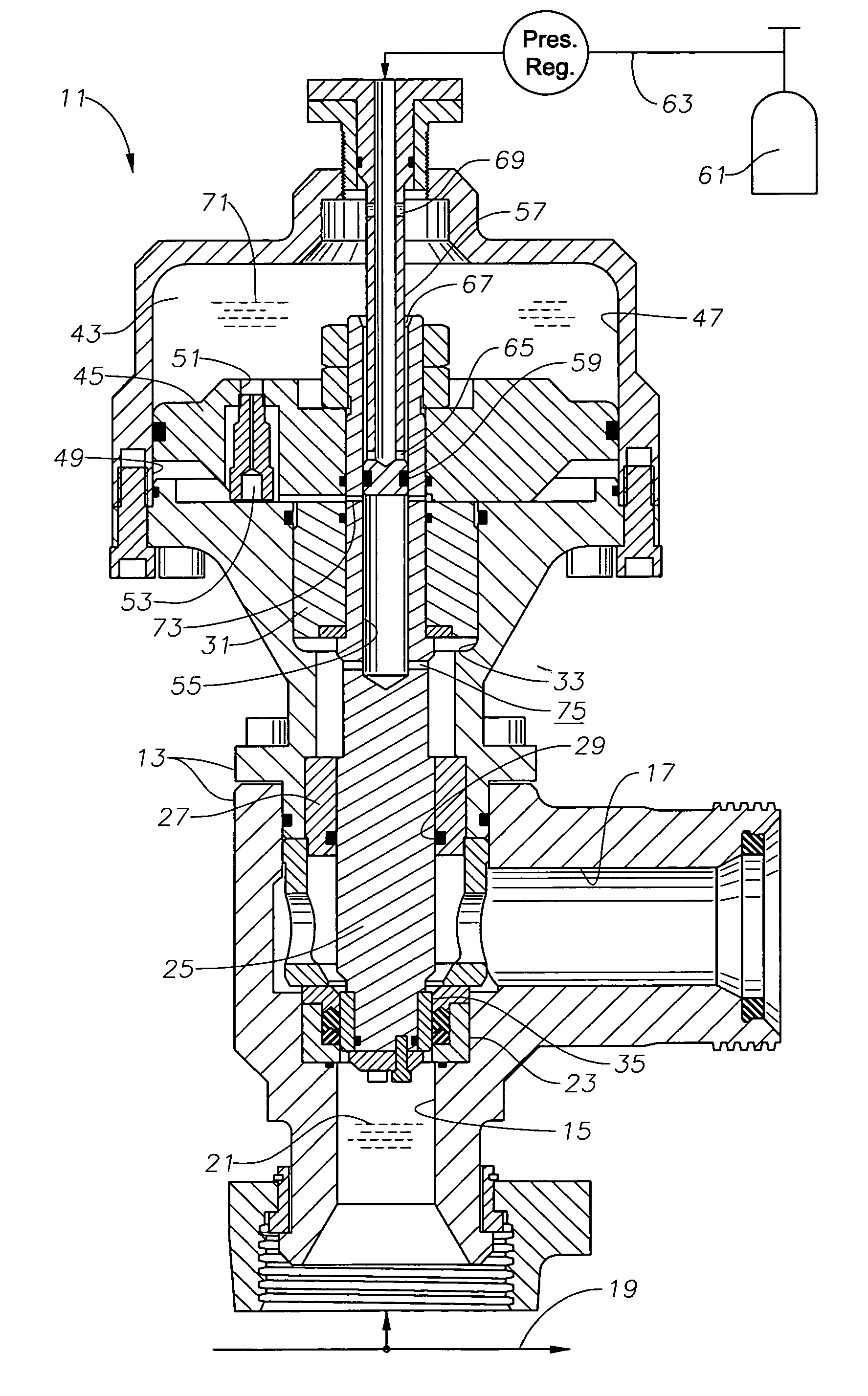
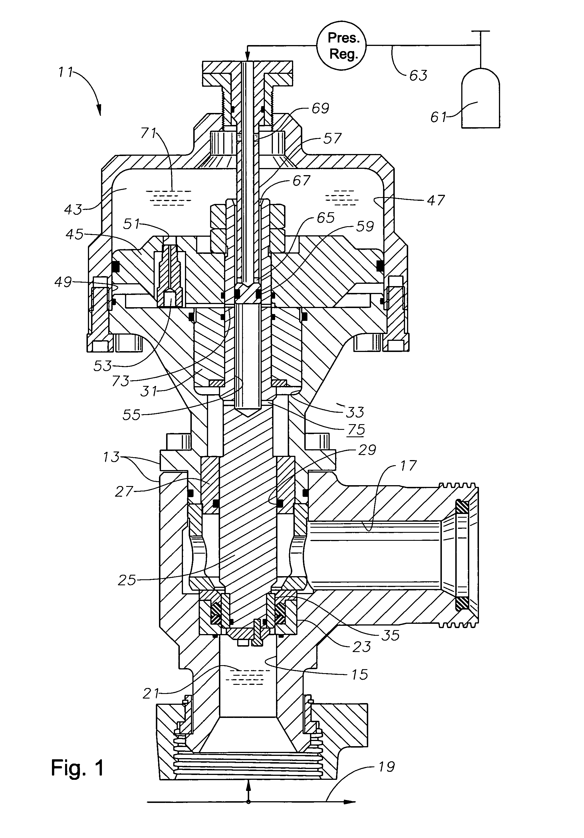
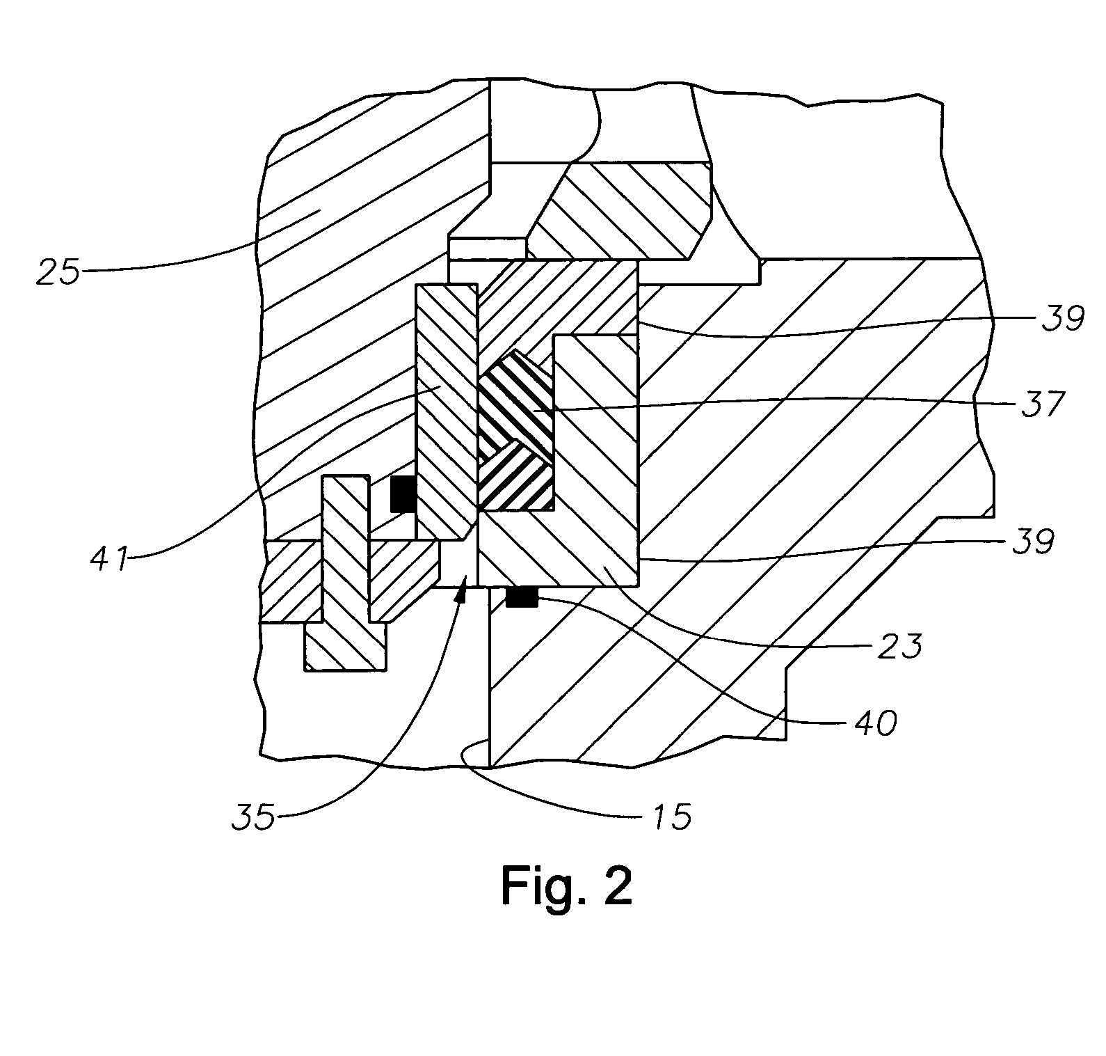
[0019]Referring to FIG. 1–4 in the drawings, the preferred embodiment of a pressure relief valve 11 according to the present invention is illustrated. Valve 11 includes a housing 13 having a wall and a relief passage with an inlet 15 and an outlet 17. Inlet 15 is situated such that its longitudinal axis intersects and forms a right angle to the longitudinal axis of outlet 17. A system line 19 is fluidly connected to inlet 15, system line 19 carrying a system fluid 21 which is introduced to valve 11 through inlet 15. A valve seat 23 is disposed within housing 13 between inlet 15 and outlet 17.

[0020]A valve member 25 having an upper end and a lower end is slidingly disposed within housing 13 so that the longitudinal axis of valve member 25 is coaxial to the axis of inlet 15. Valve member 25 passes through a partition 27. A seal 29 provides a sealing engagement between partition 27 and valve member 25. Toward its upper end, valve member 25 is engaged by a guide 31 which is disposed wit...


PUM


Abstract

A pressure relief valve has a housing fluidly connected to a pressurized system line carrying a system fluid. The housing carries a moveable piston and a valve member that both move between closed and open positions. The piston defines an upper chamber and a lower chamber within the housing. A pressurized fluid is supplied to the upper chamber to bias the piston toward the closed position. After the relief valve opens from excessive system pressure, the pressurized fluid is injected into the lower chamber to delay the return of the piston to the closed position. Initially, the fluid in the lower chamber flows through a check valve while the piston returns to the closed position. Then the fluid vent in the lower chamber vents from the lower chamber as the piston and valve member approach the closed position.

Description

BACKGROUND OF THE INVENTION[0001]1. Field of the Invention[0002]This invention relates in general to valves and in particular to an improved pressure relief valve that relieves a pressure of a system fluid by entering an open position and then by returning to the normally-closed position following a delay period.[0003]2. Description of Related Art[0004]In a fluid transport system having a system fluid with a pressure that varies, it is often desirable to relieve or lower the pressure of the system fluid if the pressure reaches an unacceptably high level. The most common way of relieving these high pressures is by use of a pressure relief valve. The pressure relief valve, which is in fluid communication with the system fluid, is designed to detect an unacceptable pressure level and relieve the pressure by opening the valve and allowing the system fluid to escape the system line.[0005]A problem sometimes develops in the use of these valves in systems that experience rapidly varying pr...

Claims


Application Information

Patent Timeline
Patent Type & Authority Patents(United States)
IPC IPC(8): F16K17/02
CPCF16K17/02Y10S137/906Y10T137/7853Y10T137/7904
Inventor KUGELEV, VLADIMIRMATZNER, MARK D.
Owner SPM OIL & GAS INC
Why Eureka
Try Eureka