System and method for operating and locking a trigger of a welding gun

a technology of welding gun and trigger, which is applied in the field of welding system, can solve the problems of time-consuming assembling the welding gun with the trigger locking assembly, significant heat generation within the handle of the welding gun, and difficult operation of the trigger or trigger lock

Inactive Publication Date: 2005-12-27
ILLINOIS TOOL WORKS INC
View PDF13 Cites 38 Cited by
  • Summary
  • Abstract
  • Description
  • Claims
  • Application Information

AI Technical Summary

Problems solved by technology

In addition, a significant amount of heat may be generated within the handle of a welding gun, especially near the neck.
However, operation of a trigger or

Method used


Image

  • System and method for operating and locking a trigger of a welding gun
  • System and method for operating and locking a trigger of a welding gun
  • System and method for operating and locking a trigger of a welding gun

Examples


Embodiment Construction

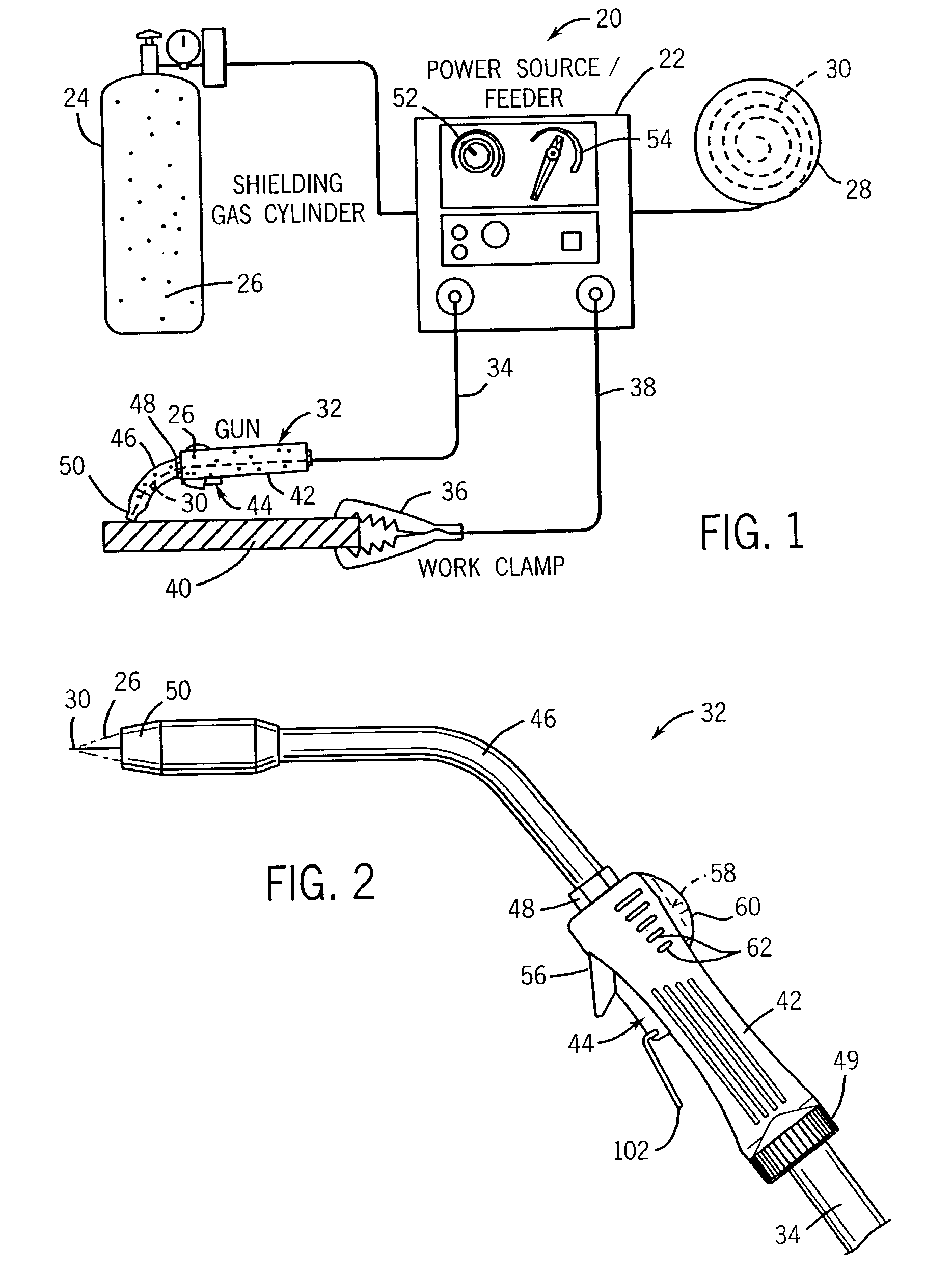
[0023]Referring generally to FIG. 1, an exemplary wire-feed metal inert gas (“MIG”) welding system 20 is illustrated. However, the present invention is operable with a variety of welding systems, such as TIG welding or submerged-arc welding. The illustrated MIG welding system 20 comprises a power source / wire feeder 22, a gas cylinder 24 containing a gas 26 that is coupled to the power source / wire feeder 22, a spool 28 of electrode wire 30 that is coupled to the power source / wire feeder, a welding gun 32, a welding cable 34, a work clamp 36, and a return cable 38.

[0024]The power source / wire feeder 22 is a source of electric power and directs the feeding of gas 26 and wire 30 to the welding cable 34. The welding cable 34 is operable to route gas 26 and wire 30 from the power source / wire feeder 22 to the welding gun 32. The work clamp 36 is clamped onto the conductive workpiece 40 to be welded. The work clamp 36 and the return cable 38 electrically couple the power source / wire feeder 2...


PUM

PropertyMeasurementUnit
Poweraaaaaaaaaa
Lengthaaaaaaaaaa

Abstract

A welding system having a welding gun. The welding gun is adapted with a trigger. The welding gun may have a lever to lock the trigger in a desired pivoted position. The lever may pivot the trigger as the lever is pivoted. The welding gun may have a trigger extension to enable a user to pivot the trigger by depressing the trigger extension. The trigger extension may be plastically deformed. The trigger extension may be removable. The trigger extension may be rotatable.

Description

FIELD OF THE INVENTION[0001]The present invention relates generally to welding systems, and particularly to a welding system having a welding gun.BACKGROUND OF THE INVENTION[0002]Welding is a method of joining, or separating, metal objects. Arc welding is a common type of welding. An arc welding system typically is comprised of a power supply coupled by an electrical cable to a welding gun housing an electrode. A ground cable is used to connect the metal object to the power supply. The electrode in the welding handle completes an electrical circuit between the power supply and the metal object when the electrode is placed against the metal object, allowing electrical current to flow through the electrode and metal object. The electrical current produces an arc between the electrode and the metal object. The heat of the electric arc melts the object in the region surrounding the electric arc. A filler material may be added to the molten metal. For example, a wire may be placed agains...

Claims


Application Information

Patent Timeline
IPC IPC(8): B23K9/10B23K9/173B23K9/29B23K9/32
CPCB23K9/10B23K9/173B23K9/295B23K9/32
Inventor CENTNER, ROBERT J.
Owner ILLINOIS TOOL WORKS INC
Why Eureka
Try Eureka