
Charge transfer device and a driving method thereof and a driving method for solid-state image sensing device

a solid-state image and transfer device technology, applied in the direction of color television details, television system details, television systems, etc., can solve the problems of reducing the number of charges handled in the vertical charge transfer portion and reducing the transfer efficiency, and achieve the effect of increasing the number of stages

Inactive Publication Date: 2005-12-27
SONY CORP
View PDF6 Cites 10 Cited by
  • Summary
  • Abstract
  • Description
  • Claims
  • Application Information

AI Technical Summary

Benefits of technology

[0005]The object of the present invention is to solve the aforementioned problems by providing a charge transfer device and a driving method thereof and a driving method for a solid-state image sensing device, more particularly, by providing a driving method for a solid-state image sensing device being able to suppress the decrease in the handling quantity of electric charges to the utmost when transferring signal charges at a high speed in the vertical charge transfer portion.
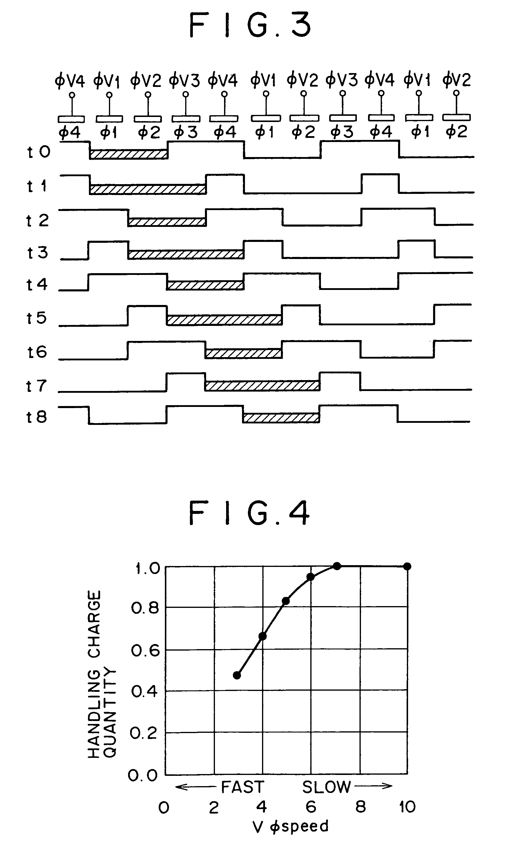
[0009]As described in the above, according to the present invention, it is made possible to increase the handling charge quantity in the vertical charge transfer portion without changing time for transfer in the vertical transfer period, so that in a case where signal charges are transferred at a high speed in the vertical charge transfer portion, for example, in a case of response to the read-out of all pixels being output independently, to the improvement of techniques in an electronic zoom lens or the correction of blur caused by an unintentional hand move, or to an increase in the number of stages in the vertical transfer, it is made possible to suppress the decrease in the handling charge quantity to the utmost.

Problems solved by technology

Then the quantity of charges handled in the vertical charge transfer portion is decreased, and there is a fear that the transfer efficiency is lowered.

Method used


Image

  • Charge transfer device and a driving method thereof and a driving method for solid-state image sensing device
  • Charge transfer device and a driving method thereof and a driving method for solid-state image sensing device
  • Charge transfer device and a driving method thereof and a driving method for solid-state image sensing device

Examples


Embodiment Construction

[0016]An explanation of embodiments of the present invention will be given in detail with reference to the drawings as follows.

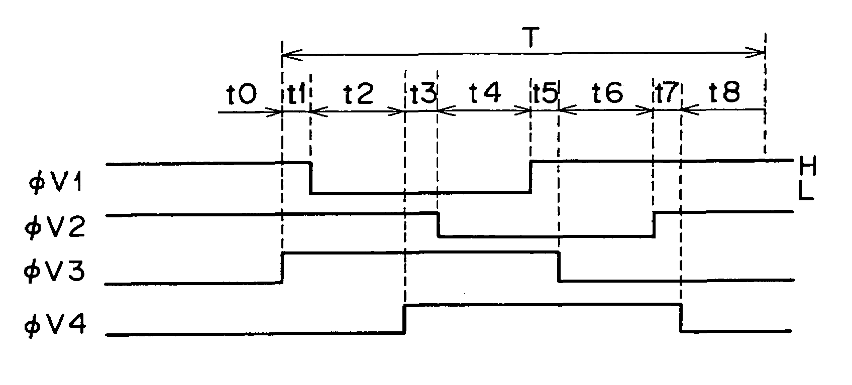
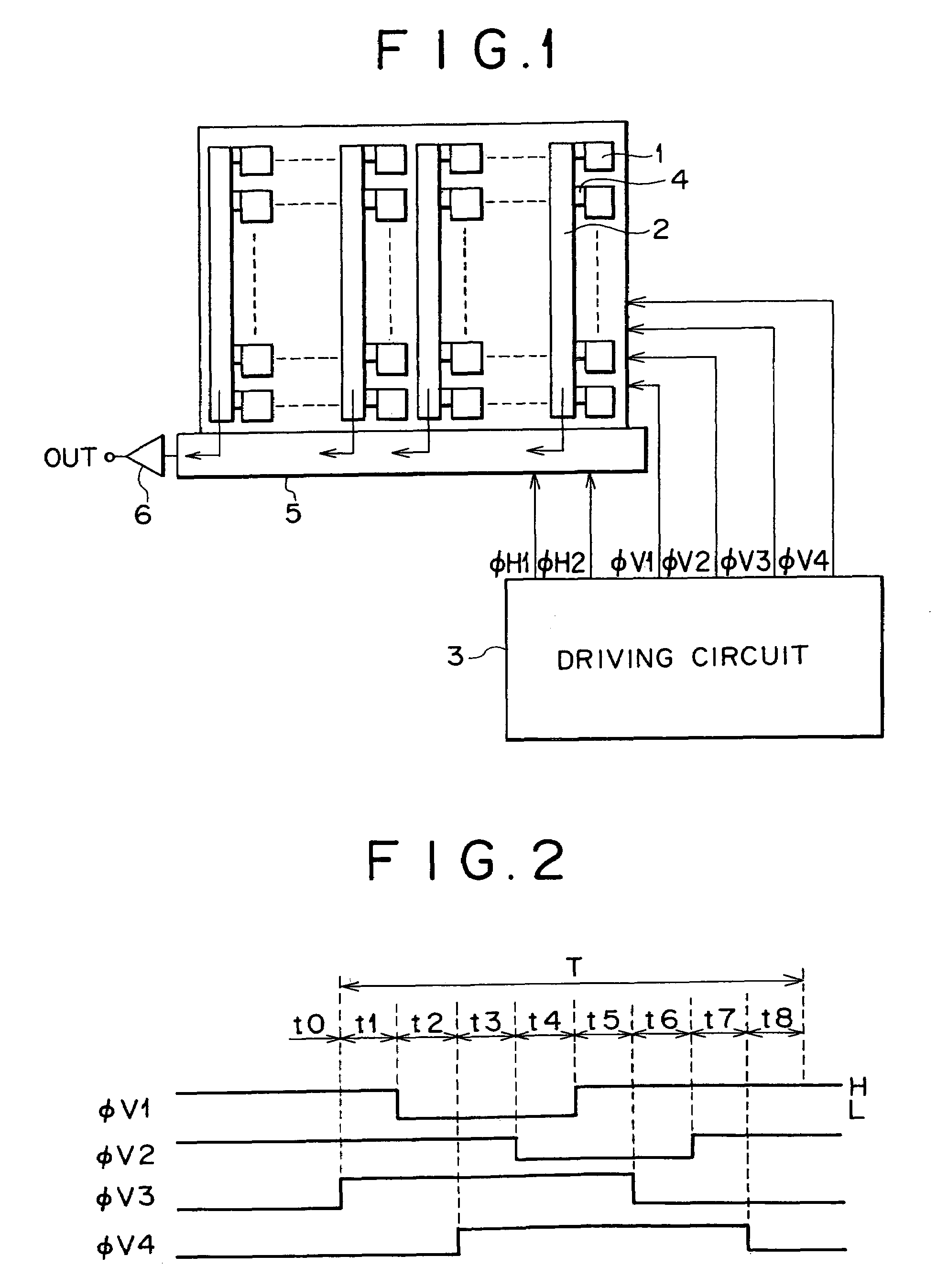
[0017]FIG. 1 shows a schematic view illustrating the constitution of a CCD area sensor of an IT type and its driving system. In the figure, a sensor portion 1 is formed of namely, photodiodes being disposed two-dimensionally in a horizontal and a vertical directions. Each sensor portion 1 converts the incident light supplied thereto to signal charges having the quantity corresponding to the light quantity and accumulates them. Plural bars of vertical charge transfer portions 2 are disposed in the vertical direction between respective sensor portions 1. Each vertical transfer portion 2 is formed of a CCD (Charge Coupled Device), and the transfer electrodes of four systems are disposed along its disposed direction. These vertical charge transfer portions 2 are driven by vertical driving pulses of 4-phase from φV1 through φV4, supplied from a driving circuit 3,...


PUM


Abstract

A driving method for a solid-state image sensing device having a plurality of sensor portions being disposed two-dimensionally in a horizontal and a vertical directions, and a vertical charge transfer portion being disposed between said plurality of sensor portions and being provided with transfer electrodes of a plurality of systems disposed along its disposed direction, including the steps of; selectively applying high level driving pulses to the transfer electrodes of said plurality of systems in respective sectional periods in a vertical transfer period, and transferring the signal charges read out from said plurality of sensor portions in the vertical direction, wherein a sectional period in a vertical transfer period, in which the number of systems of the transfer electrodes to be applied with high level driving pulses becomes minimum is set longer than that of the other sectional periods. It is thus made possible to increase the handling charge quantity in the vertical charge transfer portion without changing time for transfer in the vertical transfer period.

Description

RELATED APPLICATION DATA[0001]The present application claims priority to Japanese Application No. P10-156944 filed Jun. 5, 1998, which application is incorporated herein by reference to the extent permitted by law.BACKGROUND OF THE INVENTION[0002]The present invention relates to a charge transfer device, such as a CCD and a driving method thereof, and a driving method for a solid-state image sensing device, in particular, it relates to a driving method for CCD solid-state image sensing devices of an IT (Inter-line Transfer) type.[0003]In general, in a CCD solid-state image sensing device of the IT type, when signal charges are transferred, for example, by a vertical charge transfer portion (vertical shift register) having transfer electrodes of four systems, the transfer of signal charges for one line is performed in a horizontal blanking interval, and normally it is performed in a vertical transfer period being composed of eight sectional periods. In respective sectional periods, e...

Claims


Application Information

Patent Timeline
IPC IPC(8): H04N5/335H04N5/341H04N5/369H04N5/3728
CPCH04N3/1531H04N3/1537H04N3/1575H04N25/73
Inventor OOKI, HIROAKI
Owner SONY CORP
Learn More