Mid-span gas bearing

a gas bearing and multi-stage technology, applied in the field of compressors, can solve the problems of increasing the number of stages in the centrifugal, limiting the operating speed and output of the machine, and causing forced respons

Active Publication Date: 2013-08-01
NUOVO PIGNONE TECH SRL
View PDF3 Cites 5 Cited by
  • Summary
  • Abstract
  • Description
  • Claims
  • Application Information

AI Technical Summary

Benefits of technology

[0018]Systems and methods according to these exemplary embodiments provide for an increase in the number of stages in a centrifugal compressor while overcoming problems typically associated with such an increase.

Problems solved by technology

An increase in the number of stages in a centrifugal compressor leads to multiple problems.
When operating at higher speeds, the decrease in the fundamental natural frequencies of the rotor assembly tends to make the system more susceptible to rotor-dynamic instability, which can limit the operating speed and output of the machine.
The other issue is the forced response due to synchronous rotor imbalance.
When the operating speed coincides with a rotor natural frequency, the machine is defined to be operating at a critical speed, which is a result of rotor imbalance.
This results in low damped rotor modes and high amplification factors at rotor resonances that can lead to casing and impeller rubs and even catastrophic failure of the machine.
At higher speeds past the rotor critical speeds, fluid induced forces are generated between the rotor assembly and the casing (i.e. fluid induced rotor dynamic instability).
These pulsations, stemming from fluid forces can excite destructive or even catastrophic vibrations if not adequately dampened.
Rotor-dynamic instability is a different mechanism from critical speeds or imbalance response and often time is much more difficult to address.

Method used


Image

  • Mid-span gas bearing
  • Mid-span gas bearing
  • Mid-span gas bearing

Examples


Embodiment Construction

[0026]The following detailed description of the exemplary embodiments refers to the accompanying drawings. The same reference numbers in different drawings identify the same or similar elements. Also, the following detailed description does not limit the invention. Instead, the scope of the invention is defined by the appended claims.

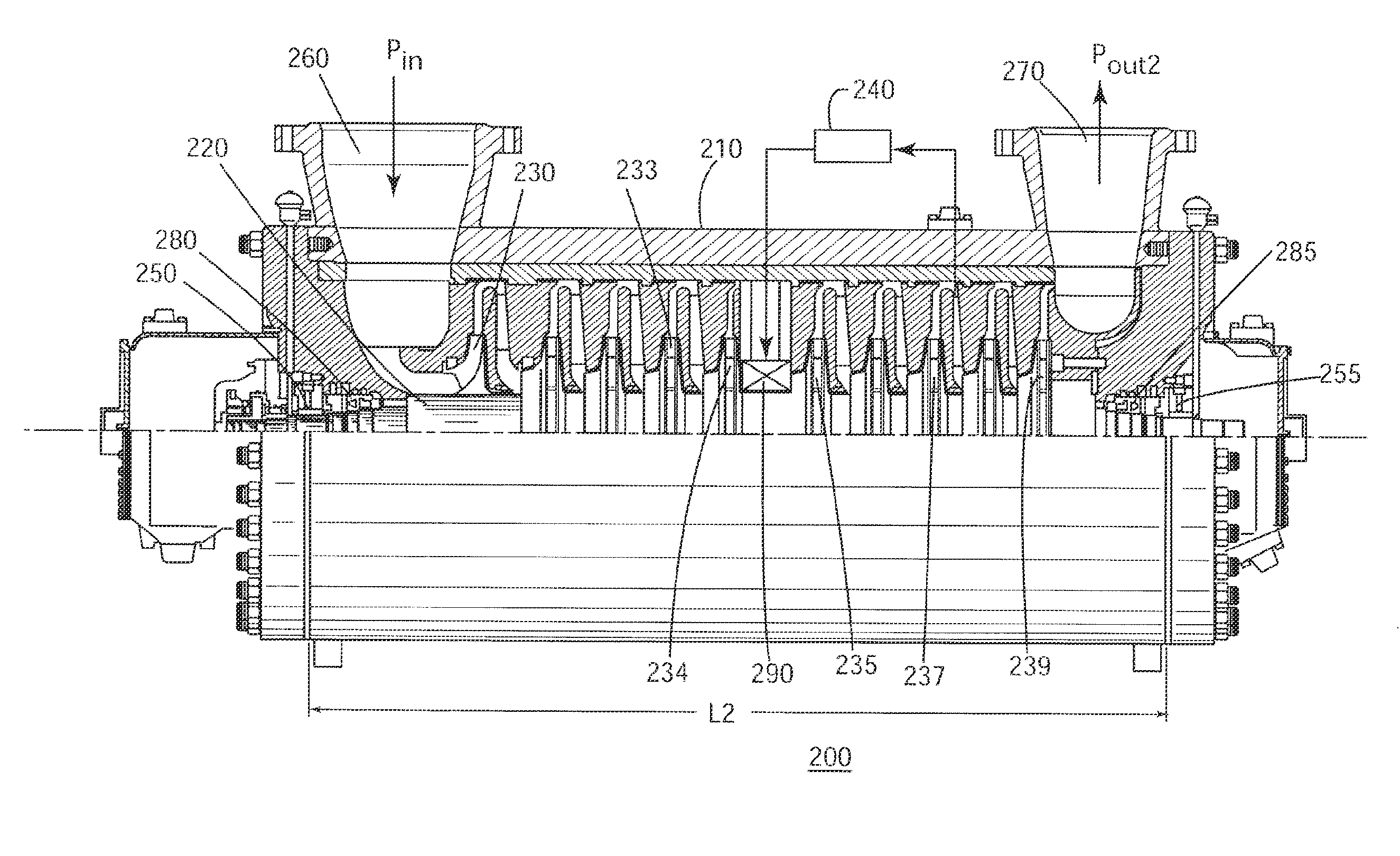
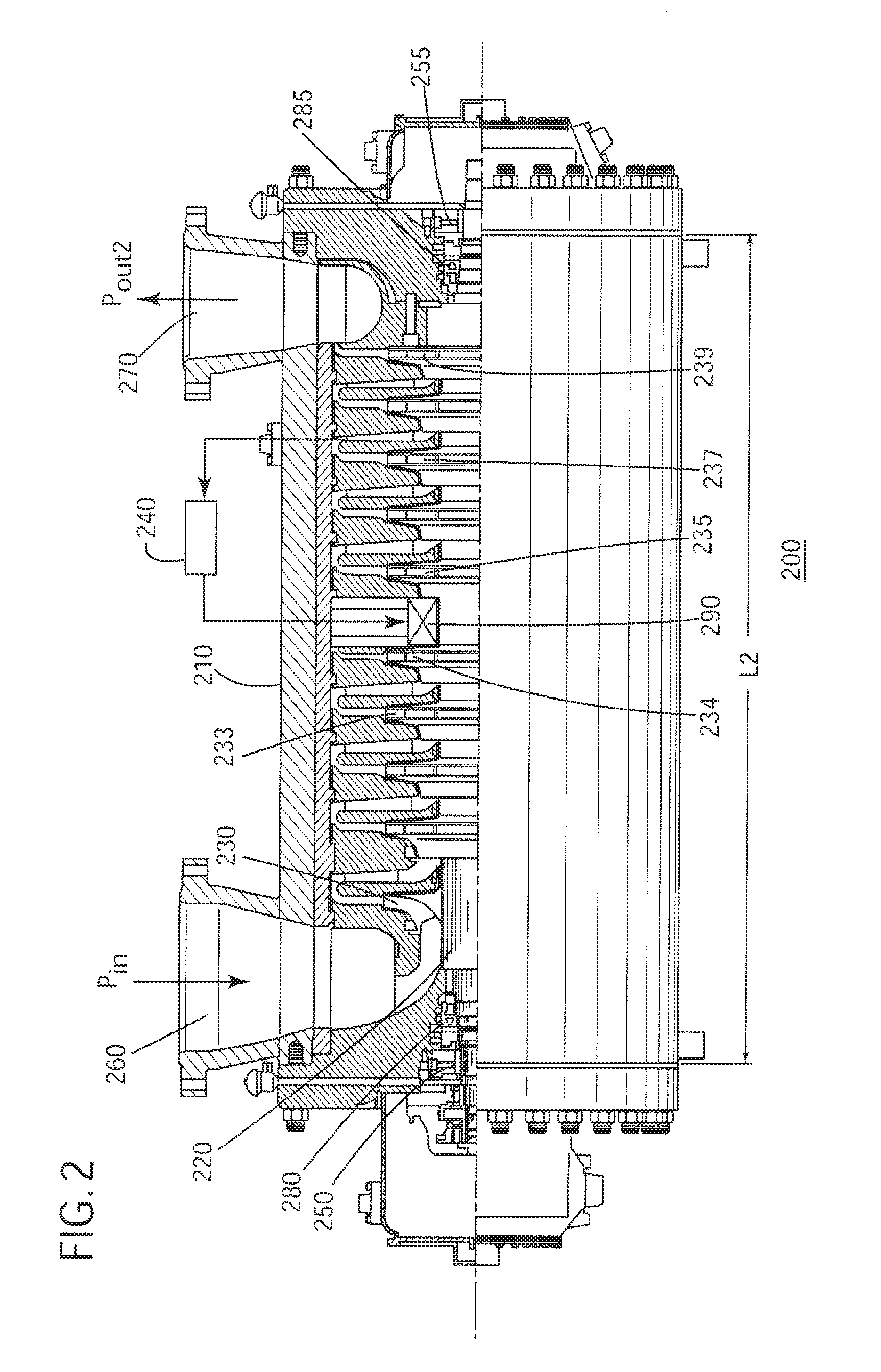
[0027]In exemplary embodiments, a mid-span bearing may be utilized to provide additional stiffness to the rotor assembly with a longer shaft to overcome the critical speed issue highlighted above. Such a bearing makes the rotor assembly less flexible and therefore allows the rotor-dynamic energy (due to synchronous rotor imbalance forces) to be transmitted to the bearings.

[0028]This three-bearing configuration increases the damping in the rotor modes and lowers amplification factors as the rotor traverses through the critical speed allowing for safe operation of the rotor assembly. A mid-span bearing may, therefore, be provided within the casing for fac...


PUM


Abstract

A centrifugal compressor includes a rotor assembly with a shaft and a plurality of impellers, bearings located at ends of the shaft and configured to support the rotor assembly, a sealing mechanism disposed between the rotor assembly and the bearings, and a gas bearing disposed between the plurality of impellers for supporting the shaft and receiving a working gas from an impeller downstream from a location of the gas bearing.

Description

CROSS REFERENCE TO RELATED APPLICATIONS[0001]This is a national stage application under 35 U.S.C. §371(c) prior-filed, co-pending PCT patent application serial number PCT / EP2010 / 069347, filed on Dec. 10, 2010, which claims priority to Italian Patent Application No. CO2009A000067, filed on Dec. 17, 2009, the entire contents of which are incorporated herein by reference.BACKGROUND OF THE INVENTION[0002]1. Field of the Invention[0003]Embodiments of the present invention relate generally to compressors and, more specifically, to a mid-span gas bearing in a multistage compressor.[0004]2. Description of the Prior Art[0005]A compressor is a machine which increases the pressure of a compressible fluid, e.g., a gas, through the use of mechanical energy. Compressors are used in a number of different applications and in a large number of industrial processes, including power generation, natural gas liquification and other processes. Among the various types of compressors used in such processes...

Claims


Application Information

Patent Timeline
Patent Type & Authority Applications(United States)
IPC IPC(8): F04D29/056
CPCF04D29/057F04D29/056F04D29/102F04D29/059F04D17/122Y10S417/00Y10S415/00F05D2240/50F05D2210/12
Inventor MARIOTTI, GABRIELECAMATTI, MASSIMOERTAS, BUGRA HANPALOMBA, SERGIO
Owner NUOVO PIGNONE TECH SRL
Why Eureka
Try Eureka