Devices and methods for producing multiple x-ray beams from multiple locations

a technology of multiple locations and x-ray beams, applied in the direction of x-ray tubes, x-ray tube cathode assemblies, nano-informatics, etc., can solve the problems of cost and efficiency, single electron beam based x-ray, limited viewing angles, etc., and achieve high-integration multiple functions, flexible controllability, and efficient production

Inactive Publication Date: 2005-12-27
NURAY TECH
View PDF30 Cites 111 Cited by
  • Summary
  • Abstract
  • Description
  • Claims
  • Application Information

AI Technical Summary

Benefits of technology

[0024]According to the present invention, devices and techniques are provided that are more efficient in producing multi-beam x-rays, provide more flexible controllability and are equipped with highly integrated multiple functions. According to the present invention, an x-ray source that can provide x-ray beams shooting to the scanned objects from different angles is provided.
[0026]According to the present invention, a field emission cathode which comprises nanostructure materials is used in the x-ray tubes as electron source for generating x-rays in this invention. This new x-ray generation mechanism provides many advantages over the conventional thermionic based x-ray source in the sense of eliminating the heating element, operating at room temperature, generating pulsed x-ray radiation in a high repetition rate and making multi-beam x-ray source and portable x-ray devices possible.

Problems solved by technology

Although the above listed techniques can serve the purpose, these single electron beam based x-ray inspection have several drawbacks related to limitations in resolution, limited viewing angles, cost and efficiency.
These prior devices and techniques suffer from a common drawback in that they all rely on one single source of electrons to generate x-rays and obtain multiple images of the PCBs from different angles.
Thus, inherently they are slow and cannot simultaneously generate multiple images of the object under inspection from different angles.
In addition, they all require mechanical motion of either the x-ray source or the x-ray detector, which will lead to inconsistency in x-ray focus spot size and imaging quality.
Furthermore, these x-ray systems all rely on thermionic electron emitters which are sensitive to temperature, require long warm up time, and can not turn on / off easily, thus they can not be easily programmed and waste large amount energy and x-ray system lifetime.

Method used


Image

  • Devices and methods for producing multiple x-ray beams from multiple locations
  • Devices and methods for producing multiple x-ray beams from multiple locations
  • Devices and methods for producing multiple x-ray beams from multiple locations

Examples


Embodiment Construction

[0043]Exemplary arrangements and techniques according to the present invention will now be described by reference to the drawing figures.

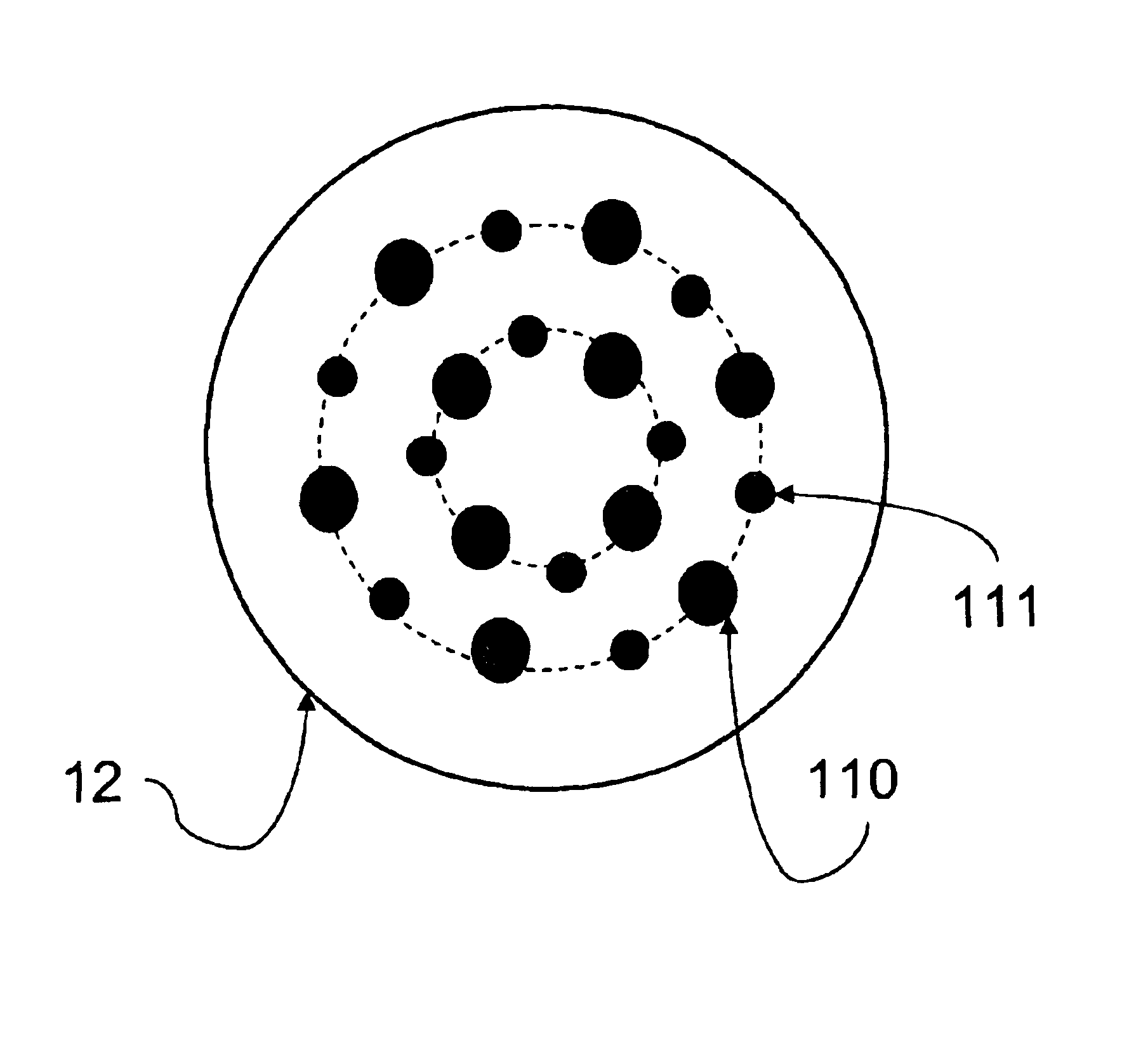
[0044]According to one embodiment of the invention, as illustrated in FIG. 5, an x-ray source comprises a field emission cathode 12 with multiple individually-addressable electron-emitting elements or “pixels”11. The cathode 12 has a planar geometry as shown in FIG. 6. The anode 13 is opposing and is separated from the cathode 12 by a finite gap distance within a vacuum chamber 14. Electron emission from the pixels 11 on the cathode can be controlled by a gate electrode. Details of possible gate electrode constructions and arrangements that can be utilized in this embodiment, and others, are described in later portions of the disclosure. The x-ray source may comprise a single gate electrode or more preferably a gate electrode with a plurality of individually addressable units, each unit controls a corresponding pixel 11 on the cathode 12. Electrons...


PUM


Abstract

An x-ray generating device includes at least one field-emission cold cathode having a substrate and incorporating nanostructure-containing material including carbon nanotubes. The device further includes at least one anode target. Associated methods are also described.

Description

[0001]The present application is a Continuation-in-Part of co-pending U.S. patent application Ser. No. 10 / 309,126 filed on Dec. 4, 2002, which is a Continuation of U.S. patent application Ser. No. 09 / 679,303 filed on Oct. 6, 2000, now U.S. Pat. No. 6,553,096. The present application is also a Continuation of U.S. patent application Ser. No. 10 / 448,144, filed on May 30, 2003.FIELD OF THE INVENTION[0002]The present invention is directed to devices and techniques for producing a plurality of X-ray beams from multiple locations. For example, methods and devices using a field emission cathode with a plurality of individually addressable electron-emitting pixels are contemplated. Electrons emitted from the pixels can be directed towards different focal points on the anode, thus producing multiple x-ray beams from multiple locations of the same device.BACKGROUND OF THE INVENTION[0003]Various constructions and techniques will be described below. However, nothing described herein should be c...

Claims


Application Information

Patent Timeline
Patent Type & Authority Patents(United States)
IPC IPC(8): H01J35/00H01J35/06
CPCB82Y10/00H01J35/065H01J2201/30469H01J2235/062H01J2235/068Y10S977/95
Inventor QIU, QILU, JIANPINGZHOU, OTTO Z.
Owner NURAY TECH
Why Eureka
Try Eureka