Power controller

a power controller and power coupler technology, applied in the direction of gain control, transmission monitoring, modulation, etc., can solve the problems of impedance mismatching, difficult for the power coupler to correctly detect and control the power magnitude, and a lot of energy may be wasted, so as to achieve high efficiency and high efficiency of the power controller

Inactive Publication Date: 2005-12-27
MEDIATEK INC
View PDF24 Cites 66 Cited by
  • Summary
  • Abstract
  • Description
  • Claims
  • Application Information

AI Technical Summary

Benefits of technology

[0009]It is therefore still another object of the invention to provide a power controller in which the bias of each of the stage amplifiers can be controlled. Thus, the efficiency of the power controller is high when the power is high and the efficiency of the power controller is high when the power is low.
[0010]To achieve the above-mentioned objects, a power controller includes a plurality of stage amplifiers, a plurality of matching circuits, at least one power detector, and a bias control circuit. The stage amplifiers receive emission signals and amplify the power thereof. The matching circuits are connected between the stage amplifiers for matching with the stage amplifiers, respectively. The power detector detects the power of the stage amplifiers and generates detection signals, respectively. The bias control circuit receives the detection signals of the power detector, thereby generating a bias of each of the stage amplifiers in order to optimize the efficiency of each of the stage amplifiers according to the magnitude of the power of each of the stage amplifiers.

Problems solved by technology

Thus, a lot of energy may be wasted.
Furthermore, since the output power at the last stage is close to the saturated region, it is difficult for the power coupler to correctly detect and control the magnitude of the power.
On the other hand, there may be a problem of impedance mismatching caused by the high power loss.
Also, the size of the power coupler 180 makes it very difficult for the device using the control system to be reduced in size.
Therefore, the energy is also wasted.

Method used


Image

  • Power controller
  • Power controller
  • Power controller

Examples


Embodiment Construction

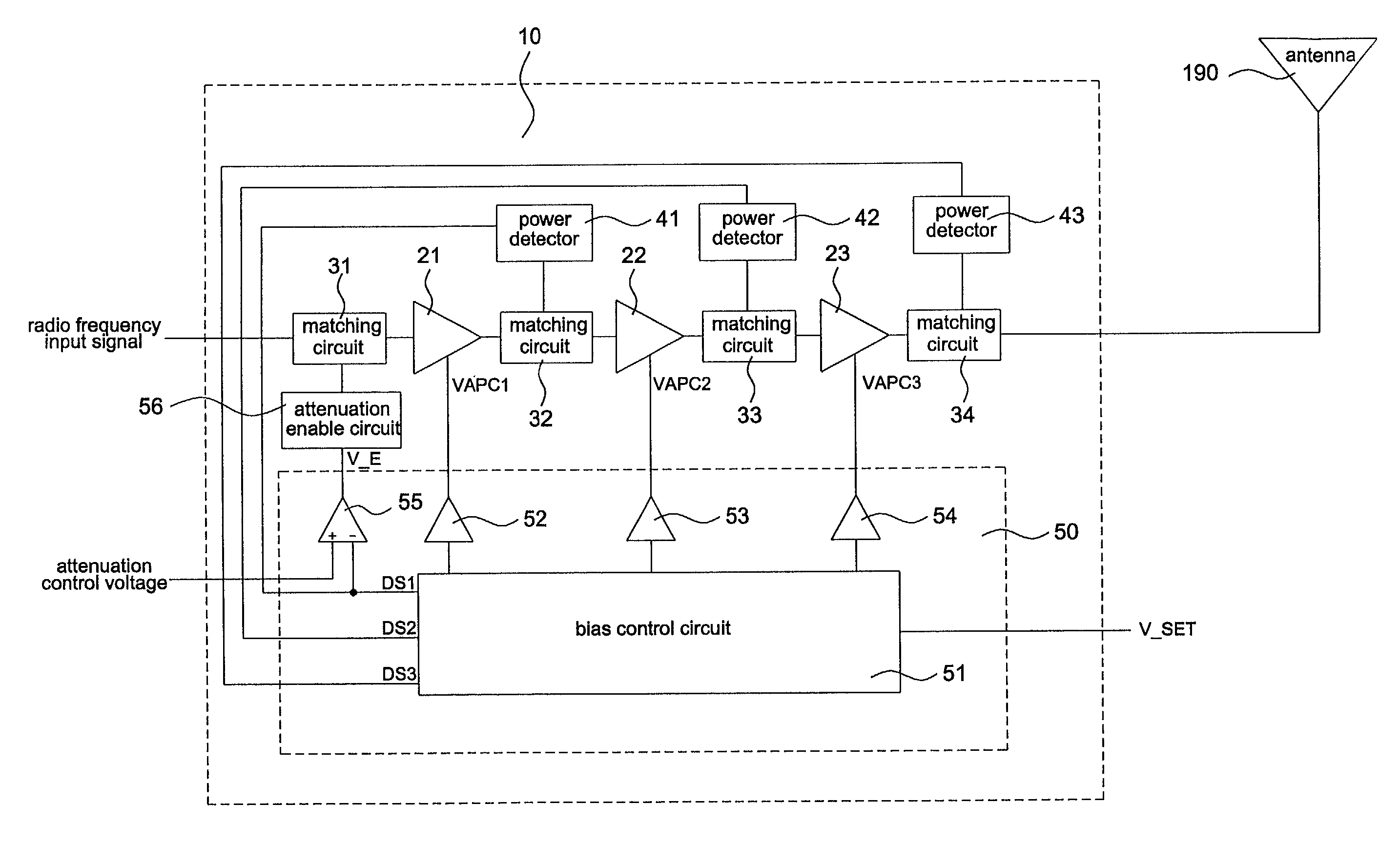
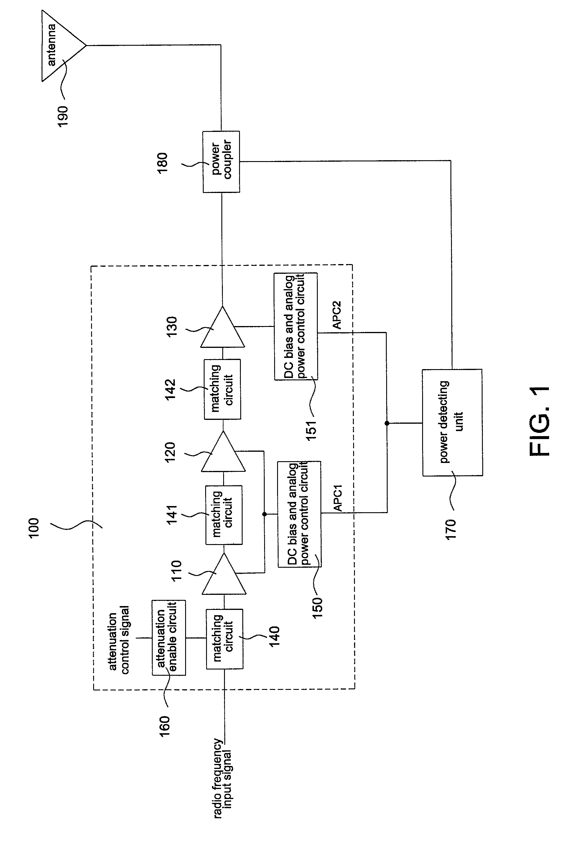
[0015]The power controller and the power control system using the controller will be described with reference to the accompanying drawings. If only the power outputted from the last stage is detected, since the power is close to the saturated region, it is difficult to detect and control the magnitude of the power. There also may be a problem of impedance mismatching caused by the high power loss. Thus, the object of the invention is to achieve a linear control by way of detecting the power outputted from the first and second stages.

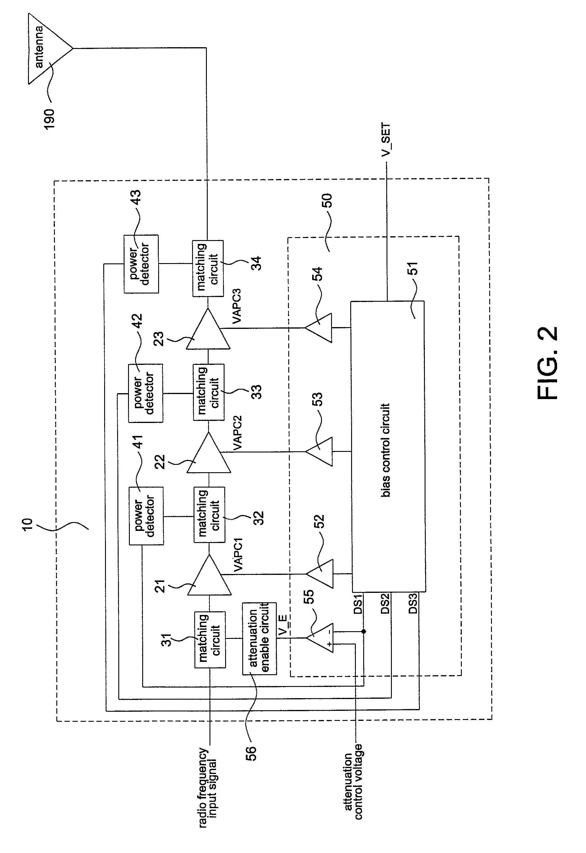
[0016]FIG. 2 is a block diagram showing the power controller of the invention, which is mainly the same as the conventional power controller. The power controller 10 also includes a driver stage amplifier 21, an inter stage amplifier 22, a power stage amplifier 23, and matching circuit 31, 32, 33, and 34. Since the functions of the amplifiers 21 to 23 and the matching circuits 31 to 34 are the same as those of the amplifiers and circuits in the conventio...


PUM


Abstract

An apparatus for power controlling in a transmitter for detecting the output power without using a power coupler includes a plurality of stage amplifiers, a plurality of matching circuits, at least one power detector, and a bias control circuit. The stage amplifiers receive an emission signal and amplify the power thereof. The matching circuits are connected between the stage amplifiers for matching with the stage amplifiers, respectively. The power detector detects the power of the stage amplifiers and generates detection signals, respectively. The bias control circuit receives the detection signals of the power detector, thereby generating a bias of each of the stage amplifiers in order to optimize the efficiency of each of the stage amplifiers according to the magnitude of the power of each of the stage amplifiers.

Description

BACKGROUND OF THE INVENTION[0001]A. Field of the Invention[0002]The present invention relates to a power controller, in particular, to a power controller in which a power detector, instead of a power coupler, is used for detecting the output power from each stage amplifier so as to effectively control the power and efficiency of each stage amplifier.[0003]B. Description of the Related Art[0004]FIG. 1 is a block diagram showing a conventional power control system. The symbol 100 refers to a GSM power controller. The function of the power controller 100 is to amplify the power of the radio frequency input signal that is emitted through an antenna 190. The power controller 100 is suitable for the power control system of the mobile phone. Referring to FIG. 1, the conventional power controller 100 includes a driver stage amplifier 110, an inter stage amplifier 120, a power stage amplifier 130, and matching circuits 140, 141, and 142 for each stage amplifier. In addition, in order to let ...

Claims


Application Information

Patent Timeline
Patent Type & Authority Patents(United States)
IPC IPC(8): H03F3/19H03G3/30H04B1/04
CPCH03F3/19H03G3/3042H04B2001/0416
Inventor CHEN, CHIEH-SHENGSU, KENG-LI
Owner MEDIATEK INC
Why Eureka
Try Eureka