Portable engine hoist

a technology of engine hoist and trailer, which is applied in the field of engine hoist, can solve the problems of difficult mounting into the drawbar of the trailer hitch, difficult to mount into the hitch, and difficult to meet the needs of transportation,

Inactive Publication Date: 2006-01-03
HENRY JAMES LOUIS
View PDF15 Cites 48 Cited by
  • Summary
  • Abstract
  • Description
  • Claims
  • Application Information

AI Technical Summary

Benefits of technology

[0015]The hoist further includes a connector member having lower and upper end portions and a first locking plate for adjustably connecting the vertical portion of the base member to the lower end thereof. The locking plate allows the connector portion to be selectively rotated in a first plane. The hoist further includes a boom having first and second end portions with the first end portion being pivotally connected to the upper end portion of the connector member and thereby allows the boom to be pivoted in a second plane substantially perpendicular to the first plane.
[0016]The hoist further includes means for pivoting the boom along the second plane that is connected to the connector member and to the first end portion of the boom. A lifting member is removably connectable to the second end portion of the boom for transporting an object from a first location to a second location. The boom preferably includes a first member having an aperture formed therein and connected to the connector member. A second member has a plurality of apertures formed therein and is alignable with the aperture of the first member so that a length of the boom can be telescopically adjusted by inserting a pin therethrough.

Problems solved by technology

Although the above-described devices operate adequately to lift objects for hauling, they each suffer from the disadvantage of difficult installation.
Furthermore, both U.S. Pat. Nos. 4,806,063 and 5,211,526 require complicated and time-consuming assembly.
Finally, U.S. Pat. No. 4,881,864 is difficult to mount into a trailer hitch drawbar because it is a single unit requiring strenuous exertion to be lifted and placed within the trailer hitch drawbar.

Method used


Image

  • Portable engine hoist
  • Portable engine hoist
  • Portable engine hoist

Examples


Embodiment Construction

[0027]The present invention will now be described more fully hereinafter with reference to the accompanying drawings, in which preferred embodiments of the invention are shown. This invention may, however, be embodied in many different forms and should not be construed as limited to the embodiments set forth herein. Rather, these embodiments are provided so that this application will be thorough and complete, and will fully convey the true scope of the invention to those skilled in the art. Like numbers refer to like elements throughout, and prime and double prime notations are used to indicate similar elements in alternate embodiments.

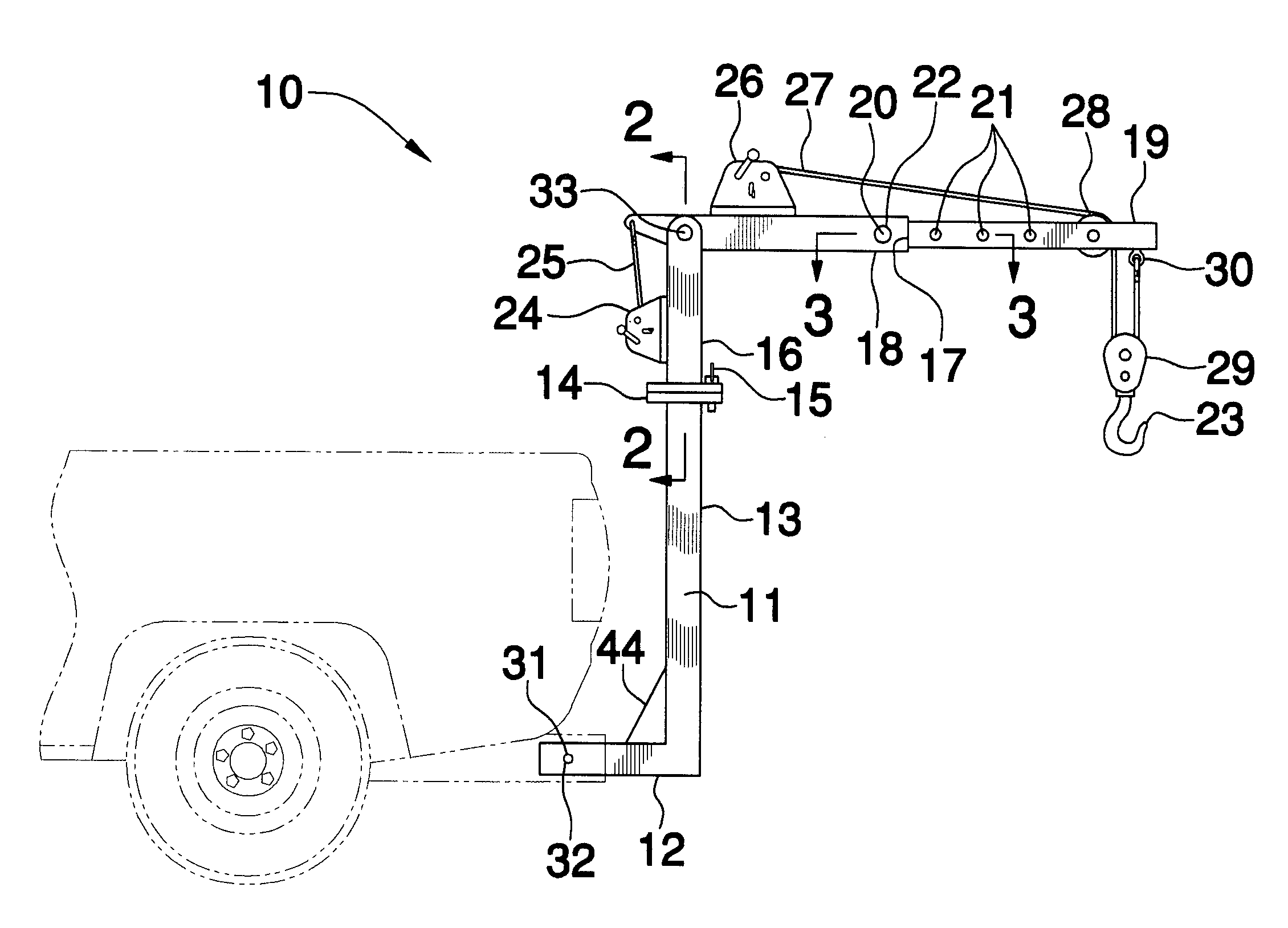
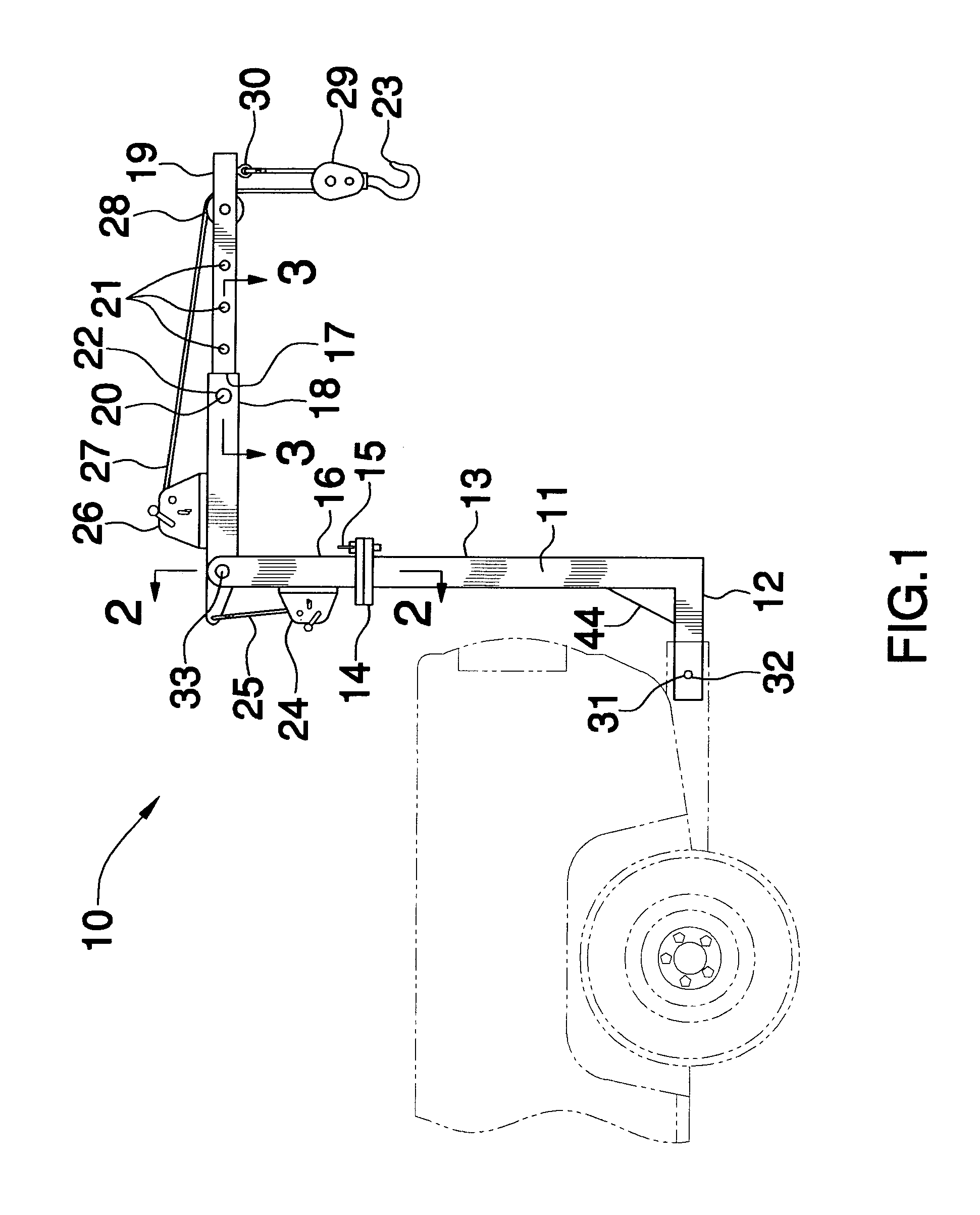
[0028]The hoist of this invention is referred to generally in FIG. 1 by the reference numeral 10 and is intended to be removably attachable to a vehicle hitch or drawbar for transporting an engine in a relatively simple manner. It should be understood that the hoist 10 may be used to transport other heavy objects and should not be limited to transport...


PUM


Abstract

A hoist includes is removably attachable to a vehicle hitch and includes a connector member and a first locking plate for adjustably connecting a base member to the connector member. The locking plate allows the connector portion to be selectively rotated in a first plane. The hoist further includes a boom pivotally connected to the connector member for allowing the boom to be pivoted in a second plane substantially perpendicular to the first plane. The hoist further includes a winch for pivoting the boom along the second plane. Alternately, a piston may pivot the boom along the second plane. A lifting member is removably connectable to the boom and for transporting an object from a first location to a second location. In an alternate embodiment, the hoist may include a manually or hydraulically operated winch for controlling the lifting member.

Description

CROSS REFERENCE TO RELATED APPLICATIONS[0001]Not Applicable.STATEMENT REGARDING FEDERALLY SPONSORED RESEARCH OR DEVELOPMENT[0002]Not Applicable.REFERENCE TO A MICROFICHE APPENDIX[0003]Not Applicable.BACKGROUND OF THE INVENTION[0004]1. Technical Field[0005]This invention relates to an engine hoist and, more particularly, to an engine hoist that is removably attachable to a trailer hitch and includes alternate lifting means.[0006]2. Prior Art[0007]The ability to use vehicles as a means for hauling objects as well as a means for transportation has always been a public concern. Consequently, various devices which mount to the rear of a vehicle to serve as a lift have been invented. One such device is disclosed in U.S. Pat. No. 2,867,402 issued on Jan. 6, 1959, to Graybill et al. Graybill et al. disclose an angled post with hooks at an upper end and a bumper clamp at the opposite end. The bumper clamp facilitates the mounting of the shaft to the rear bumper of a vehicle, while the hooks ...

Claims


Application Information

Patent Timeline
Patent Type & Authority Patents(United States)
IPC IPC(8): B60P9/00
CPCB60P1/5476B60P1/5471B66C23/44
Inventor HENRY, JAMES LOUIS
Owner HENRY JAMES LOUIS
Why Eureka
Try Eureka