

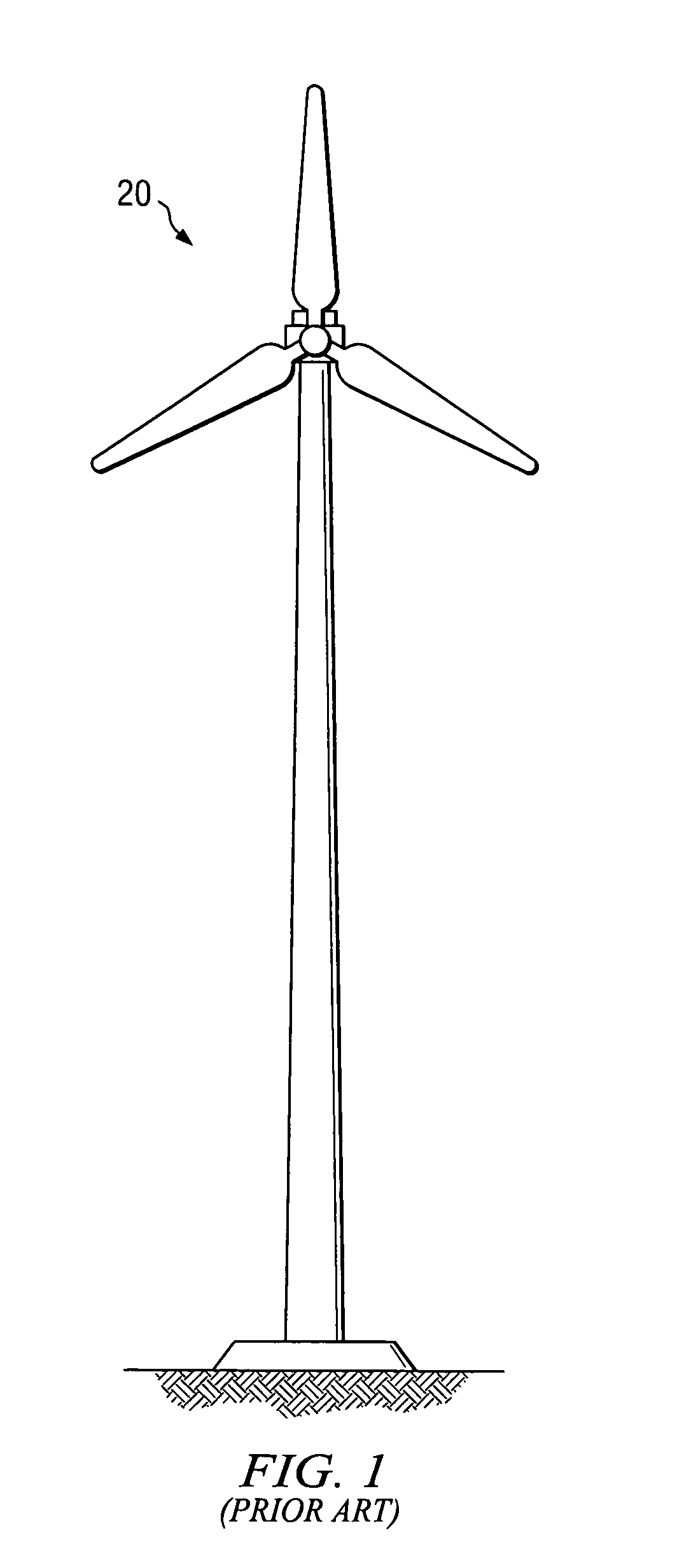
Wind powered turbine in a tunnel
a tunnel-type, wind-powered technology, applied in the direction of electric generator control, renewable energy generation, greenhouse gas reduction, etc., can solve the problems of wind-powered generators that are difficult/or too expensive to build in large scal
- Summary
- Abstract
- Description
- Claims
- Application Information
AI Technical Summary
Benefits of technology
Problems solved by technology
Method used
Image

Examples
Embodiment Construction
[0028]Referring now to the drawings, wherein like reference numbers are used herein to designate like or similar elements throughout the various views, illustrative embodiments of the present invention are shown and described. The figures are not necessarily drawn to scale, and in some instances the drawings have been exaggerated and / or simplified in places for illustrative purposes only. One of ordinary skill in the art will appreciate the many possible applications and variations of the present invention based on the following illustrative embodiments of the present invention.
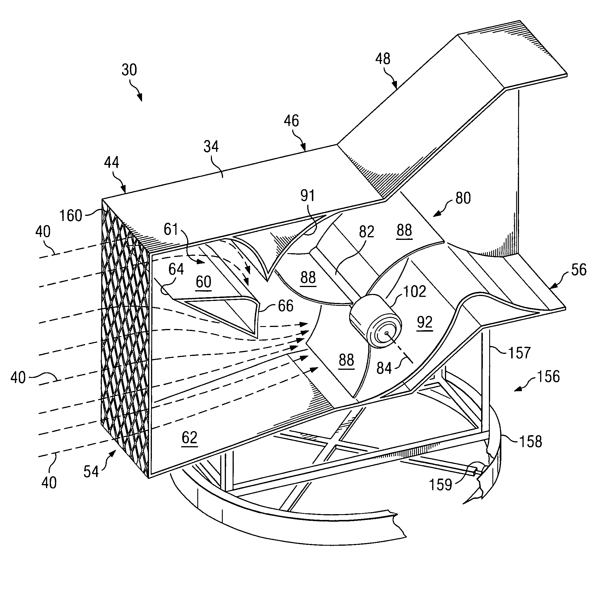
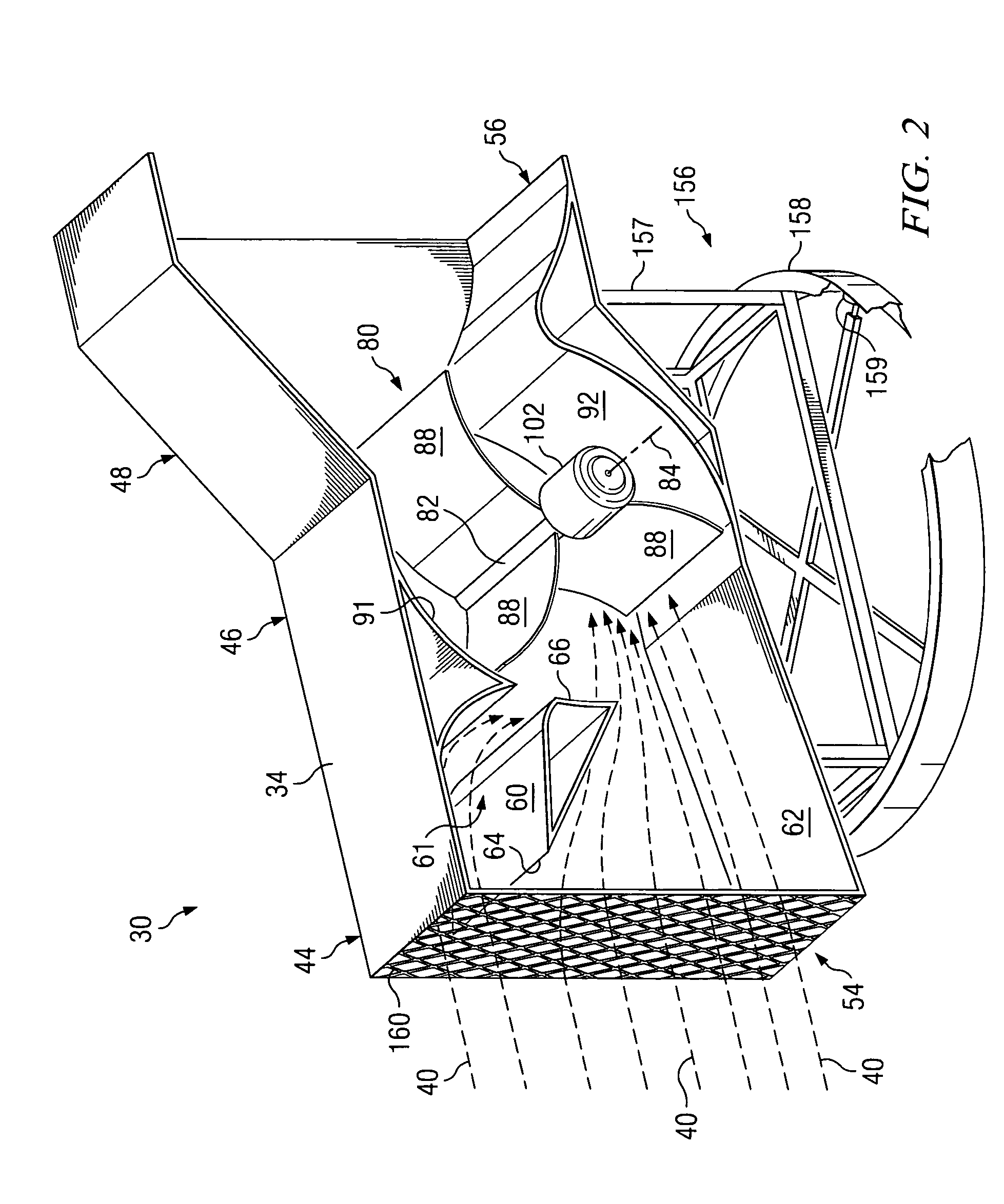
[0029]Generally, an embodiment of the present invention provides a wind powered turbine. The illustrative wind powered turbines shown herein are adapted for use in generating electricity, for example, by having generators coupled thereto. However, an embodiment of the present invention may have other uses, as will be apparent to one of ordinary skill in the art having the benefit of this disclosure. FIGS. 2-5...
PUM
 Abstract
Description
Claims
Application Information