System and method for operating transmit or transmit/receive elements in an MR system

a technology of transmitting element and receiving element, which is applied in the field of system and method for operating elements in phased array coils for magnetic resonance imaging, can solve the problems of high power dissipation, high energy dissipation in the tissue of the patient, and higher temperature of the scanner

Active Publication Date: 2006-01-03
TEXAS A&M UNIVERSITY +1
View PDF5 Cites 52 Cited by
  • Summary
  • Abstract
  • Description
  • Claims
  • Application Information

AI Technical Summary

Benefits of technology

[0015]Another advantage of the present invention is independent control of current amplitudes and phases on the current elements over a wide range of drive voltage amplitudes.

Problems solved by technology

Enhanced imaging sequences typically demand high amplitude gradient fields, rapid field transitions, and large duty cycles in order to improve resolution and scan time unfortunately, these properties also drive the power dissipation higher and thus cause higher temperatures in the scanner.
At these high frequencies a further problem is that a high amount of energy may be dissipated in the tissue of the patient, which is generally undesirable.
Due to strong coupling between the rungs of a resonant coil and sensitivity to loading, such independent control has not been possible and homogeneity optimization involves a time consuming and impractical iterative procedure in the absence of exact knowledge of interactions among coil elements and between the coil and load.

Method used


Image

  • System and method for operating transmit or transmit/receive elements in an MR system
  • System and method for operating transmit or transmit/receive elements in an MR system
  • System and method for operating transmit or transmit/receive elements in an MR system

Examples


Embodiment Construction

[0024]In each of the following figures, the same reference numerals are used to refer to the same components. The present invention is described with respect to an MRI control method and apparatus for high field MR scanners including: MRI systems, magnetic resonance spectroscopy systems, and other applications where scan homogeneity is desirable.

[0025]In the following description, various operating parameters and components are described for one constructed embodiment. These specific parameters and components are included as examples and are not meant to be limiting.

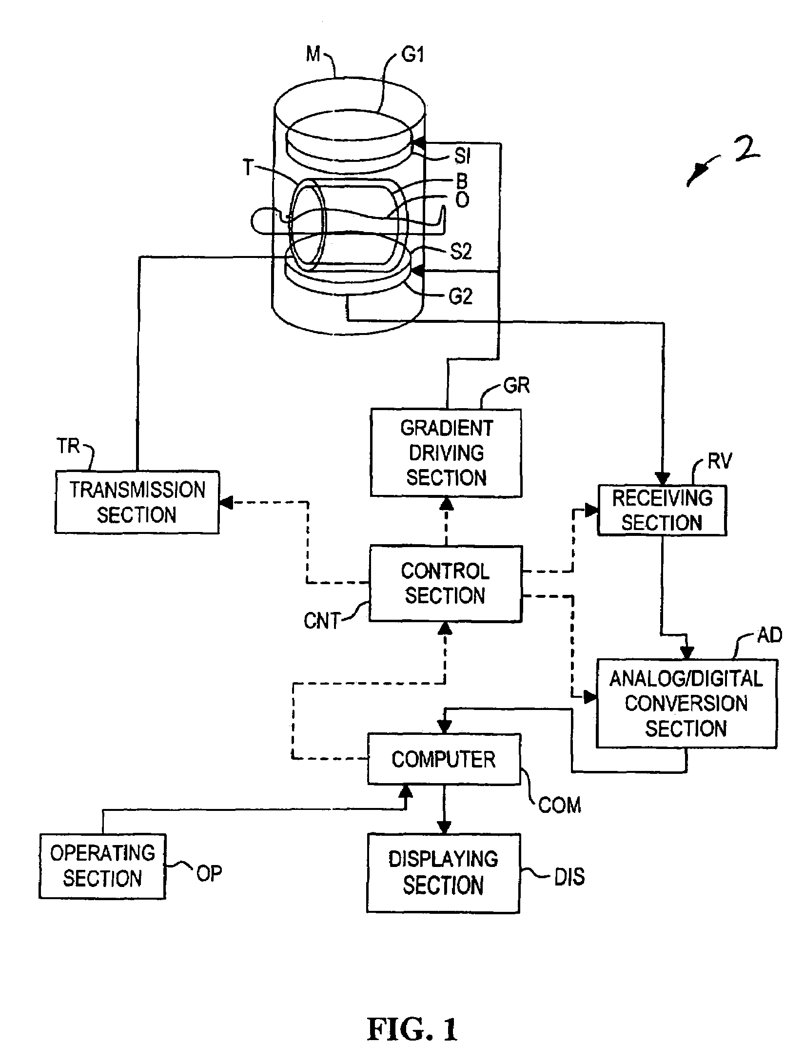
[0026]Referring now to FIG. 1, there is shown a block diagram of an MRI system 2 operable to perform a magnetic resonance imaging by using a radio frequency coil according to the present invention.

[0027]The system ofFIG. 1 is operated such that a static magnetic field generating section M may form a uniform static magnetic field in its inner space. The static magnetic field generating section M is comprised of a pair of ...


PUM


Abstract

An MRI system includes an array of series resonant transmit elements 6 and 65 including individual control of RF current in all elements 106, 108, 110, 114, 116, 118, 120. The array 6 and 65 adjusts scan homogeneity during a scan or prescan phase by adjusting amplitude and phase. The array 6 and 65 also selectively excites areas of interest, thus avoiding major power dissipation and avoiding heating in the patient.

Description

TECHNICAL FIELD[0001]The present invention relates generally to Magnetic Resonance Imaging (MRI) systems, and more particularly, to a system and method for operating elements in phased array coils for Magnetic Resonance Imaging.BACKGROUND OF THE INVENTION[0002]Magnetic Resonance Imaging (MRI) is a well-known procedure for obtaining detailed, two and three-dimensional images of patients based on nuclear magnetic resonance (NMR) principles. MRI is well suited for the imaging of soft tissues and is primarily used for diagnosing internal injuries.[0003]Typical MRI systems include a magnet capable of producing an intense, homogenous magnetic field around a patient or portion of the patient; a radio frequency (RF) transmitter and receiver system, including a receiver coil also surrounds a portion of the patient; a magnetic gradient system localizes a portion of the patient; and a computer processing / imaging system, which receives the demodulated signals from the receiver system and proces...

Claims


Application Information

Patent Timeline
Patent Type & Authority Patents(United States)
IPC IPC(8): G01V3/00G01R33/34G01R33/36
CPCG01R33/34046G01R33/3628G01R33/3614
Inventor KURPAD, KRISHNA NAGARAJWRIGHT, STEVEN M.BOSKAMP, EDDY BENJAMIN
Owner TEXAS A&M UNIVERSITY
Why Eureka
Try Eureka