Method of driving DC motor and related circuit for avoiding reverse current

a technology of dc motor and reverse current, which is applied in the direction of motor/generator/converter stopper, electronic commutator, dynamo-electric converter control, etc., can solve the problems of large capacitor size, damage to circuit, and serious damage to power supply devices

Active Publication Date: 2012-05-22
ANPEC ELECTRONICS CORPORATION
View PDF4 Cites 786 Cited by
  • Summary
  • Abstract
  • Description
  • Claims
  • Application Information

AI Technical Summary

Benefits of technology

[0016]Therefore, the main objective of the present invention is to provide a DC motor control method to avoid the reverse current induced by the Back Electromotive Force.
[0018]The present invention further discloses a direct-current (DC) motor control circuit for driving a DC motor, which avoids the occurrence of reverse current induced by the Back Electromotive Force, and the control circuit comprises a power supply unit for providing a driving current to drive the DC motor; a comparing unit for comparing a signal level of a terminal of the DC motor with a predetermined voltage value to produce a comparing result; and a control unit for controlling a specific lower gate switch to avoid the occurrence of a reverse current of the DC motor according to the comparing result.

Problems solved by technology

The aforementioned reverse current may damage the circuit under some conditions.
However, since the power switch PSW4 is shut off, so the motor current can only be directed to the power switch PSW1, passing the endpoint VM1, and then directed to the power supply device 100, and this reverse current may seriously damage the power supply device 100.
However, in order to prevent any damage to the circuit, the capacitance of the bypass capacitor CVM1 (as well as the size of the capacitor CVM1) needs to be of a larger value (and so the size of the capacitor will become larger); this will increase the component cost and take more space out of the printed circuit board.
However, the happening of the Back Electromotive Force VBEMF1 is a natural consequence of the running DC motor MOTOR1, and cannot be avoided.
By the way, U.S. Pat. No. 7,411,367 discloses a DC motor driving method for preventing another kind of reverse current occurring while switching between the first motor driving state and the second motor driving state, and is not designed for preventing the reverse current induced from instantaneous change from the heavy load to the light load within the same motor driving state.

Method used


Image

  • Method of driving DC motor and related circuit for avoiding reverse current
  • Method of driving DC motor and related circuit for avoiding reverse current
  • Method of driving DC motor and related circuit for avoiding reverse current

Examples


Embodiment Construction

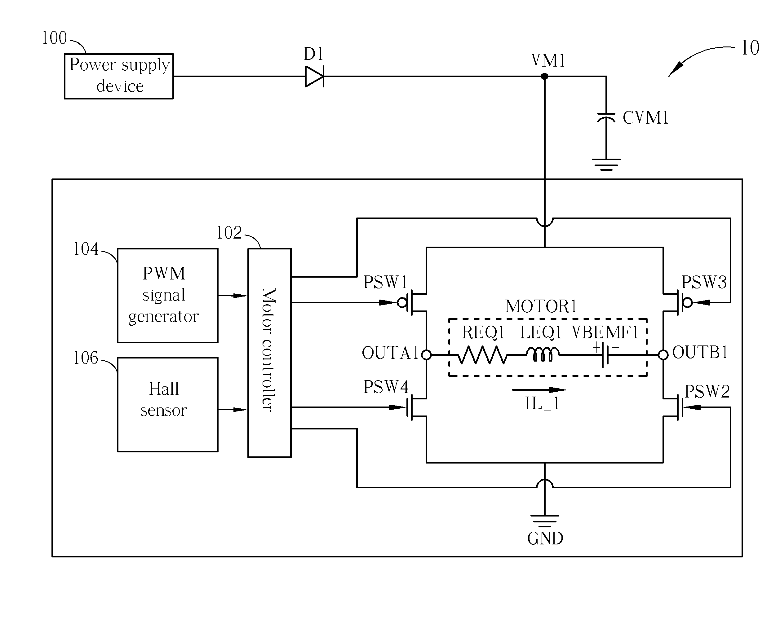
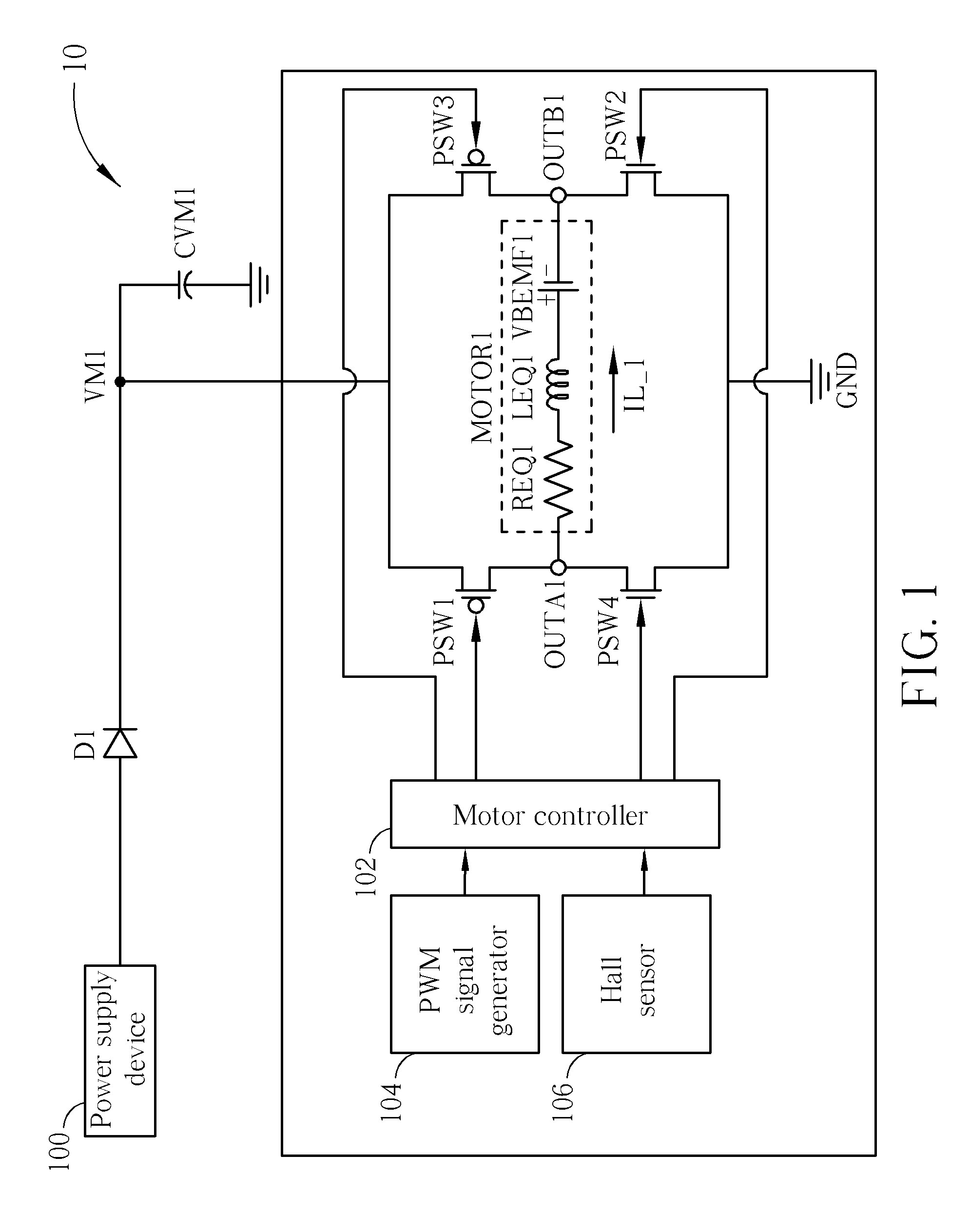
[0032]To completely solve the reverse current problem, please refer to FIG. 4, which illustrates an architecture diagram of a DC motor control circuit 40 according to an embodiment of the present invention. The DC motor control circuit 40 is utilized to control a DC motor MOTOR0, and includes a power supply 400, power switches SW1˜SW4, a comparing unit 402, a control unit 404 and a multiplexer 406. The power switches SW1˜SW4 constitute an H bridge. The power supply 400 is used to supply electric power to the motor MOTOR0 and the rest of the circuit. The comparing unit 402 is utilized to compare the voltage level of motor terminals (OUTA or OUTB) with a predetermined voltage value VREF, such that a comparing result CS can be generated. The control unit 404 is utilized to control the switching operations of the power switches SW1˜SW4 according to the comparing result CS. Besides this, the DC motor control circuit 40 further comprises a PWM signal generator 410 and a Hall sensor 420, a...


PUM


Abstract

A motor driving method for driving a direct-current (DC) motor, designed for avoiding a reverse current induced by the Back Electromotive Force (BEMF), includes providing a driver circuit for driving the DC motor; comparing a signal level of a terminal of the DC motor and a predetermined voltage value to produce a comparing result; and controlling a specific lower gate switch to avoid the occurrence of a reverse current of the DC motor according to the comparing result.

Description

BACKGROUND OF THE INVENTION[0001]1. Field of the Invention[0002]The present invention is related to a DC motor control method for avoiding the reverse current, and more particularly, to a DC motor control method which can prevent the reverse current induced by Back Electromotive Force (BEMF) inherent in a DC motor.[0003]2. Description of the Prior Art[0004]A DC (direct current) motor has very wide application in our everyday life. For example, fans installed on a CPU, or on a casing of a personal computer or inside a projector, and these are the cases which the DC motor are used for dissipating heat; other cases like stirrers, toys or robots are also using DC motors for various purposes. Generally speaking, the working principle of a DC brushless motor is to conduct a current through a stator coil of the DC motor to generate a magnetic field, and then the magnetic field is interacted with the magnetic field of a rotor (armature) to generate mechanical torque. Meanwhile, the DC motor...

Claims


Application Information

Patent Timeline
Patent Type & Authority Patents(United States)
IPC IPC(8): H02P6/18
CPCH02P6/18
Inventor TSAI, MING-JUNGLI, CHING-SHENGCHEN, KUN-MIN
Owner ANPEC ELECTRONICS CORPORATION
Why Eureka
Try Eureka